P0203-FUEL INJECTOR 3 CIRCUIT
P0203-FUEL INJECTOR 3 CIRCUIT
 |
For a complete wiring diagram, refer to the Wiring Information.
Theory of Operation
The fueling strategy for the Powertrain control Module (PCM) requires potentially three fuel pulses per cylinder per cycle. The first pulse is delivered starting at a programmed angle soon after the intake valve closes, for specified time duration. This is for two reasons, first to prevent any fuel from this pulse being delivered in the previous cycle and second to allow fueling to begin as early as possible in the current cycle. The second pulse is delivered for a specified time and is set to end at a programmed angle. The pulse must not extend past the end angle. There can be a separate value for each cylinder under the same operating conditions. This is done for two reasons, one to prevent any fuel from this pulse being delivered during the intake/exhaust valve overlap period, which tends to cause elevated emission levels. Also, allowing fuel to enter each cylinder at a slightly different angle tends to reduce any fuel pressure standing waves in the fuel rail. If the desired total fuel pulse-width increases, a third fuel pulse must be delivered. The third pulse, if necessary, is delivered for a specified time and must end at a programmed angle before the valve closes again. The third pulse in the cycle is controlled by its ending angle. This is also for two reasons, first to prevent any fuel from this pulse being delivered in the next cycle and second to allow fueling to end as late as possible in the current cycle. At high engine speeds, one or more of the pulses may be dropped from the fueling strategy.
-
When Monitored:
With battery voltage greater than 10.0 Volts. Auto Shutdown Relay energized. Engine speed less than 3000 RPM.
-
Set Condition:
The Powertrain Control Module (PCM) monitors the continuity of the injector circuits as well as the voltage spike created by the collapse of the magnetic field in the injector coil. Any condition that reduces the maximum current flow or the magnitude of the voltage spike can cause this DTC to set.
Possible Causes |
|---|
| (F342) ASD RELAY OUTPUT CIRCUIT |
| (K13) INJECTOR CONTROL 3 CIRCUIT OPEN |
| (K13) INJECTOR CONTROL 3 CIRCUIT SHORTED TO GROUND |
| FUEL INJECTOR |
| POWERTRAIN CONTROL MODULE (PCM) |
Always perform the Pre-Diagnostic Troubleshooting procedure before proceeding. (Refer to 28 - DTC-Based Diagnostics/MODULE, Powertrain Control (PCM) - Standard Procedure).
| 1. | Turn the ignition on. |
| 2. | With the scan tool, select View DTCs. Record DTC and Freeze Frame information. |
| 3. | Start the engine and allow it to reach operating temperature. |
When the engine is operating, do
not stand in direct line with the fan. Do not put your hands near
the pulleys, belts or fan. Do not wear loose clothing. Failure to
follow these instructions may result in possible serious or fatal
injury.
WARNING:
| NOTE: | Review Freeze Frame information. Operate the vehicle under conditions similar to which the DTC was set. |
| 4. | With the scan tool, select View DTCs. |
Is the DTC Active at this time?
Yes
- Go To 2
No
- Perform the INTERMITTENT CONDITION diagnostic procedure. (Refer to 28 - DTC-Based Diagnostics/MODULE, Powertrain Control (PCM) - Standard Procedure).
2. FUEL INJECTOR 3 CIRCUIT RESISTANCE
| 1. | Turn the ignition off. |
| 2. | Disconnect the PCM C2 harness connector. |
| 3. | Remove the ASD Relay. |
| NOTE: | The resistance of the circuit will vary according to the temperature of the injector coil. Use the table below to determine the resistance range of the injector. |
| 4. | Measure the resistance of the Fuel Injector 3 circuit from the PCM C2 harness connector and the ASD Relay socket. |
Fuel Injector Coil Resistance Based on Engine Temperature |
|
|---|---|
Temperature |
Resistance |
| -20°C (-4°F) | 10 Ohms (+/- .6 Ohm) |
| 20°C (68°F) | 12 Ohms (+/- .6 Ohm) |
| 60°C (140°F) | 14 Ohms (+/- .6 Ohm) |
| 100°C (212°F) | 16 Ohms (+/- .6 Ohm) |
Is the resistance of the injector within the specified range?
Yes
- Go To 7
No
-
Go To 3
3. FUEL INJECTOR 3 WIRING AND CONNECTOR INSPECTION
| 1. | Turn the ignition off. |
| 2. | Disconnect the Fuel Injector 3 harness connector and inspect the terminals for any condition that would result in a poor connection. |
| 3. | Using the wiring diagram/schematic as a guide, inspect the Fuel Injector 3 wiring and connector. |
Were there any issues?
Yes
- Repair as necessary.
- Perform the POWERTRAIN VERIFICATION TEST. (Refer to 28 - DTC-Based Diagnostics/MODULE, Powertrain Control (PCM) - Standard Procedure).
No
- Go To 4
4. (F342) ASD RELAY OUTPUT CIRCUIT OPEN OR HIGH RESISTANCE
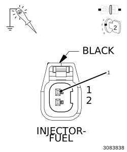 |
| 1. | Install the ASD Relay. |
| 2. | Connect the PCM C2 harness connector. |
| 3. | Turn the ignition on. |
| 4. | With the scan tool, actuate the Auto Shutdown (ASD) Relay Control State. |
| 5. | Using a 12-Volt test light connected to ground, check the (F342) ASD Relay Output circuit in the Fuel Injector 3 harness connector. |
| NOTE: | The test light should be illuminated and bright. Compare the brightness to that of a direct connection to the battery. |
Is the test light illuminated and bright?
Yes
- Go To 5
No
- Repair the excessive resistance or short to ground in the (F342) ASD Relay Output circuit.
-
Perform the POWERTRAIN
VERIFICATION TEST. (Refer to
28 - DTC-Based Diagnostics/MODULE, Powertrain Control (PCM)
- Standard
Procedure).
5. (K13) INJECTOR 3 CONTROL CIRCUIT OPEN OR HIGH RESISTANCE
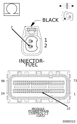 |
| 1. | Measure the resistance of the (K13) Injector 3 Control circuit between the Fuel Injector 3 harness connector and the PCM C2 harness connector. |
Is the resistance below 5.0 Ohms?
Yes
- Go To 6
No
- Repair the excessive resistance or open in the (K13) Injector 3 Control circuit.
-
Perform the POWERTRAIN
VERIFICATION TEST. (Refer to
28 - DTC-Based Diagnostics/MODULE, Powertrain Control (PCM)
- Standard
Procedure).
| 1. | Using the wiring diagram/schematic as a guide, inspect the wiring and connectors between the Fuel Injector 3 and the Powertrain Control Module (PCM). |
Were there any issues?
Yes
- Repair as necessary.
- Perform the POWERTRAIN VERIFICATION TEST. (Refer to 28 - DTC-Based Diagnostics/MODULE, Powertrain Control (PCM) - Standard Procedure).
No
- Replace the Fuel Injector in accordance with the Service Information. (Refer to 14 - Fuel System/Fuel Injection/INJECTOR(S) , Fuel - Removal).
- Perform the POWERTRAIN VERIFICATION TEST. (Refer to 28 - DTC-Based Diagnostics/MODULE, Powertrain Control (PCM) - Standard Procedure).
7. (K13) INJECTOR 3 CONTROL CIRCUIT SHORTED TO GROUND
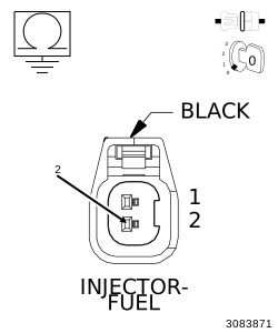 |
| 1. | Turn the ignition off. |
| 2. | Disconnect the PCM C2 harness connector. |
| 3. | Measure the resistance between ground and the (K13) Injector 3 Control circuit in the Fuel Injector 3 harness connector. |
Is the resistance above 100 Ohms?
Yes
- Go To 8
No
- Repair the (K13) Injector 3 Control circuit for a short to ground.
-
Perform the POWERTRAIN
VERIFICATION TEST. (Refer to
28 - DTC-Based Diagnostics/MODULE, Powertrain Control (PCM)
- Standard
Procedure).
8. POWERTRAIN CONTROL MODULE (PCM)
| 1. | Using the wiring diagram/schematic as a guide, inspect the wiring and connectors between the Fuel Injector 3 and the Powertrain Control Module (PCM). |
Were there any issues?
Yes
- Repair as necessary.
- Perform the POWERTRAIN VERIFICATION TEST. (Refer to 28 - DTC-Based Diagnostics/MODULE, Powertrain Control (PCM) - Standard Procedure).
No
- Replace and program the Powertrain Control Module (PCM) in accordance with the Service Information. (Refer to 08 - Electrical/8E - Electronic Control Modules/MODULE, Powertrain Control - Removal) .
- Perform the POWERTRAIN VERIFICATION TEST. (Refer to 28 - DTC-Based Diagnostics/MODULE, Powertrain Control (PCM) - Standard Procedure).