P0390-CAMSHAFT POSITION SENSOR CIRCUIT - BANK 2 SENSOR 2
P0390-CAMSHAFT POSITION SENSOR CIRCUIT - BANK 2 SENSOR 2
 |
For a complete wiring diagram, refer to the Wiring Information.
Theory of Operation
 |
| NOTE: |
The CMP sensor is a dual read sensor reading both camshafts of it's correlating bank. |
|
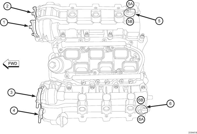
3.6L VVT Component Locations |
|
|---|---|
|
CALLOUT |
DESCRIPTION |
|
1 |
VVT Actuator Bank 1 Position 2 |
|
2 |
VVT Actuator Bank 1 Position 1 |
|
3 |
VVT Actuator Bank 2 Position 1 |
|
4 |
VVT Actuator Bank 2 Position 2 |
|
5 |
Camshaft Position Sensor 2/1 Signal |
|
6 |
Bank 2 Camshaft Sensor |
|
7 |
Camshaft Position Sensor 2/2 Signal |
|
8 |
Camshaft Position Sensor 1/2 Signal |
|
9 |
Bank 1 Camshaft Sensor |
|
10 |
Camshaft Position Sensor 1/1 Signal |
The 3.6L has four separate Camshafts that the Powertrain Control Module (PCM) requires positional information from. There are two Camshaft Position (CMP) Sensors on the 3.6L, each CMP Sensor consists of four circuits. The sensors are located on the top end of each valve cover, closest to the transmission side of the engine. The CMP Sensor is an integrated circuit sensing device and on the end of each Camshaft is a magnetic encoder that is programmed with a magnetic pattern. The PCM provides a 5-Volt supply and a sensor ground circuit to the CMP Sensor and the CMP Sensor provides two Camshaft positional signals, the intake and exhaust camshaft position, to the PCM. The sensor detects the magnetically encoded information, a series of magnetic peaks and valleys, from the encoder. As each Camshaft rotates, the magnetic encoded pattern passes by the CMP Sensor creating a changing magnetic field at the sensor face. The changing magnetic field is interpreted by the sensor electronics and a digital output, ON/OFF or HIGH/LOW pattern, is produced. The length of the pulse widths generated by the CMP varies in size based on the velocity of the Camshaft. The PCM decodes the digital pattern to identify the Camshaft position. The information from each individual Camshaft along with the Crankshaft information is used to control and sequence the Variable Valve Timing (VVT) system and fuel injection events.
-
When Monitored:
During engine cranking and with the engine running. Battery voltage greater than 10.0 volts.
-
Set Condition:
At least five seconds or 2.5 engine revolutions have elapsed with Crankshaft Position Sensor signals present but no camshaft position sensor signal. One Trip Fault. Three good trips to turn off the MIL. If the vehicle is equipped with the stop/start feature, the system will be disabled when this DTC is active.
Possible Causes |
|---|
| (F856) 5-VOLT SUPPLY CIRCUIT SHORTED TO VOLTAGE |
| (F856) 5-VOLT SUPPLY CIRCUIT OPEN |
| (F856) 5-VOLT SUPPLY CIRCUIT SHORTED TO GROUND |
| (K445) CMP SENSOR SIGNAL 2/2 CIRCUIT SHORTED TO VOLTAGE |
| (K445) CMP SENSOR SIGNAL 2/2 CIRCUIT OPEN |
| (K445) CMP SENSOR SIGNAL 2/2 CIRCUIT SHORTED GROUND |
| (K445) CMP SENSOR SIGNAL 2/2 CIRCUIT SHORTED TO THE (F856) 5-VOLT SUPPLY CIRCUIT |
| (K900) SENSOR GROUND CIRCUIT OPEN |
| CAMSHAFT POSITION SENSOR 2 |
| CRANKSHAFT POSITION SENSOR |
| POWERTRAIN CONTROL MODULE (PCM) |
Always perform the Pre-Diagnostic Troubleshooting procedure before proceeding. (Refer to 28 - DTC-Based Diagnostics/MODULE, Powertrain Control (PCM) - Standard Procedure).
| 1. | Turn the ignition on. |
| 2. | With the scan tool, read DTCs. Copy DTC and Freeze Frame information. |
| 3. | Start the engine and allow it to reach operating temperature. |
When the engine is operating, do
not stand in direct line with the fan. Do not put your hands near
the pulleys, belts or fan. Do not wear loose clothing. Failure to
follow these instructions may result in possible serious or fatal
injury.
WARNING:
| NOTE: | Attempt to operate the vehicle under conditions similar to which the DTC was set. |
| NOTE: | It may be necessary to test drive the vehicle within the DTC monitoring conditions in order for this DTC to set. |
| 4. | With the scan tool, read the active DTCs. |
Is the DTC Active at this time?
Yes
- Go To 2
No
- Go To 14
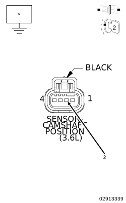
2. (F856) 5-VOLT SUPPLY CIRCUIT
 |
| 1. | Turn the ignition off. |
| 2. | Disconnect the CMP Sensor 2 harness connector. |
| 3. | Ignition on, engine not running. |
| 4. | Measure the voltage on the (F856) 5-Volt Supply circuit in the CMP Sensor harness connector. |
Is the voltage between 4.5 and 5.2 volts?
Yes
- Go To 3
No
-
Go To 10
3. (K445) CMP SENSOR SIGNAL 2/2 CIRCUIT
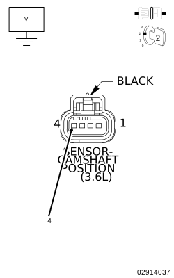 |
| 1. | Measure the voltage on the (K445) CMP Sensor Signal 2/2 circuit in the CMP Sensor 2 harness connector. |
Is the voltage between 4.5 and 5.0 volts?
Yes
- Go To 4
No
-
Go To 7
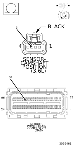
4. (K900) SENSOR GROUND CIRCUIT OPEN
 |
| 1. | Turn the ignition off. |
| 2. | Disconnect the PCM C2 harness connector. |
| 3. | Measure the resistance of the (K900) Sensor ground circuit from the CMP Sensor 2 harness connector to the PCM C2 harness connector. |
Is the resistance below 5.0 Ohms?
Yes
- Go To 5
No
- Repair the open in the (K900) Sensor ground circuit.
-
Perform the POWERTRAIN VERIFICATION TEST. (Refer to 28 - DTC-Based Diagnostics/MODULE, Powertrain Control (PCM)
- Standard Procedure).
5. (K445) CMP SENSOR SIGNAL 2/2 CIRCUIT SHORTED TO THE (F856) 5-VOLT SUPPLY CIRCUIT
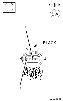 |
| 1. | Measure the resistance between the (K445) CMP Sensor Signal 2/2 circuit and the (F856) 5-Volt Supply circuit in the CMP Sensor 2 harness connector. |
Is the resistance below 5.0 Ohms?
Yes
- Repair the short between the (K445) CMP Sensor Signal 2/2 circuit and the (F856) 5-Volt Supply circuit.
- Perform the POWERTRAIN VERIFICATION TEST. (Refer to 28 - DTC-Based Diagnostics/MODULE, Powertrain Control (PCM) - Standard Procedure).
No
-
Go To 6
| NOTE: | Inspect the Camshaft sprocket for damage in accordance with the Service Information. If a problem is found repair as necessary. |
If there are no possible causes remaining, view repair.
Repair
- Verify that there is good pin to terminal contact in the CMP Sensor and Powertrain Control Module connectors. Replace the Camshaft Position Sensor 2 if no problems were found with the connectors. (Refer to 08 - Electrical/8I - Ignition Control/SENSOR, Camshaft Position - Removal) .
- Perform the POWERTRAIN VERIFICATION TEST. (Refer to 28 - DTC-Based Diagnostics/MODULE, Powertrain Control (PCM) - Standard Procedure).
7. (K445) CMP SENSOR SIGNAL 2/2 CIRCUIT SHORTED TO VOLTAGE
|
| 1. | Turn the ignition off. |
| 2. | Disconnect the PCM C2 harness connector. |
| 3. | Ignition on, engine not running. |
| 4. | Measure the voltage on the (K445) CMP Sensor Signal 2/2 circuit in the CMP Sensor 2 harness connector. |
Is there any voltage present?
Yes
- Repair the short to voltage in the (K445) CMP Sensor Signal 2/2 circuit.
- Perform the POWERTRAIN VERIFICATION TEST. (Refer to 28 - DTC-Based Diagnostics/MODULE, Powertrain Control (PCM) - Standard Procedure).
No
-
Go To 8
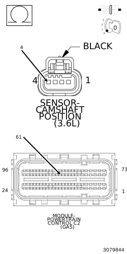
8. (K445) CMP SENSOR SIGNAL 2/2 CIRCUIT OPEN OR EXCESSIVE RESISTANCE
 |
| 1. | Turn the ignition off. |
| 2. | Measure the resistance of the (K445) CMP Sensor Signal 2/2 circuit from the CMP Sensor 2 harness connector to the PCM C2 harness connector. |
Is the resistance below 5.0 Ohms?
Yes
- Go To 9
No
- Repair the open in the (K445) CMP Sensor Signal 2/2 circuit.
-
Perform the POWERTRAIN VERIFICATION TEST. (Refer to 28 - DTC-Based Diagnostics/MODULE, Powertrain Control (PCM)
- Standard Procedure).
9. (K445) CMP SENSOR SIGNAL 2/2 CIRCUIT SHORTED TO GROUND
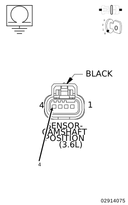 |
| 1. | Measure the resistance between ground and the (K445) CMP Sensor Signal 2/2 circuit in the CMP Sensor 2 harness connector. |
Is the resistance below 100 Ohms?
Yes
- Repair the short to ground in the (K445) CMP Sensor Signal 2/2 circuit.
- Perform the POWERTRAIN VERIFICATION TEST. (Refer to 28 - DTC-Based Diagnostics/MODULE, Powertrain Control (PCM) - Standard Procedure).
No
-
Go To 10
10. (F856) 5-VOLT SUPPLY CIRCUIT SHORTED TO VOLTAGE
|
| 1. | Turn the ignition off. |
| 2. | Disconnect the PCM C2 harness connector. |
| 3. | Ignition on, engine not running. |
| 4. | Measure the voltage on the (F856) 5-Volt Supply circuit in the CMP Sensor 2 harness connector. |
Is there any voltage present?
Yes
- Repair the short to voltage in the (F856) 5-Volt Supply circuit.
- Perform the POWERTRAIN VERIFICATION TEST. (Refer to 28 - DTC-Based Diagnostics/MODULE, Powertrain Control (PCM) - Standard Procedure).
No
-
Go To 11
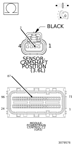
11. (F856) 5-VOLT SUPPLY CIRCUIT OPEN
 |
| 1. | Turn the ignition off. |
| 2. | Measure the resistance of the (F856) 5-Volt Supply circuit between the CMP Sensor 2 harness connector to the PCM C2 harness connector. |
Is the resistance below 5.0 Ohms?
Yes
- Go To 12
No
- Repair the open in the (F856) 5-Volt Supply circuit.
-
Perform the POWERTRAIN VERIFICATION TEST. (Refer to 28 - DTC-Based Diagnostics/MODULE, Powertrain Control (PCM)
- Standard Procedure).
12. (F856) 5-VOLT SUPPLY CIRCUIT SHORTED TO GROUND
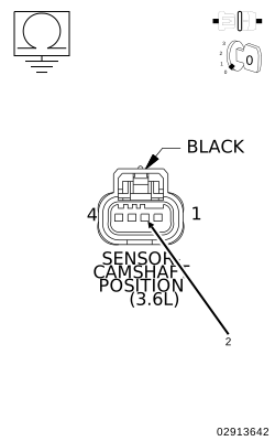 |
| 1. | Measure the resistance between ground and the (F856) 5-Volt Supply circuit in the CMP Sensor 2 harness connector. |
Is the resistance below 100 Ohms?
Yes
- Repair the short to ground in the (F856) 5-Volt Supply circuit.
- Perform the POWERTRAIN VERIFICATION TEST. (Refer to 28 - DTC-Based Diagnostics/MODULE, Powertrain Control (PCM) - Standard Procedure).
No
-
Go To 13
13. POWERTRAIN CONTROL MODULE (PCM)
| 1. | Using the wiring diagram/schematic as a guide, inspect the wiring and connectors between the related Sensor and the Powertrain Control Module (PCM). |
| 2. | Look for any chafed, pierced, pinched or partially broken wires. |
| 3. | Look for broken, bent, pushed out or corroded terminals. Verify that there is good pin to terminal contact in the related Sensor and the Powertrain Control Module connectors. |
| 4. | Perform any Technical Service Bulletins that may apply. |
Were there any problems found?
Yes
- Repair as necessary.
- Perform the POWERTRAIN VERIFICATION TEST. (Refer to 28 - DTC-Based Diagnostics/MODULE, Powertrain Control (PCM) - Standard Procedure).
No
- Replace and program the Powertrain Control Module in accordance with the Service Information. (Refer to 08 - Electrical/8E - Electronic Control Modules/MODULE, Powertrain Control - Removal) .
- Perform the POWERTRAIN VERIFICATION TEST. (Refer to 28 - DTC-Based Diagnostics/MODULE, Powertrain Control (PCM) - Standard Procedure).
| 1. | With a lab scope, back probe the (K445) CMP Sensor Signal 2/2 circuit in the CMP Sensor 2 harness connector. |
When the engine is operating, do
not stand in direct line with the fan. Do not put your hands near
the pulleys, belts or fan. Do not wear loose clothing. Failure to
follow these instructions may result in possible serious or fatal
injury.
WARNING:
| 2. | Ignition on, engine not running. |
| 3. | Wiggle the related wire harness and lightly tap the CMP Sensor. |
| 4. | Observe the lab scope screen. |
| 5. | Allow the engine to idle. |
| 6. | Observe the lab scope screen. |
Did the CMP Sensor generate any erratic pulses?
Yes
- Verify that there is good pin to terminal contact in the CMP Sensor and the Powertrain Control Module connectors. If OK, replace the Camshaft Position Sensor. (Refer to 08 - Electrical/8I - Ignition Control/SENSOR, Camshaft Position - Removal) .
- Perform the POWERTRAIN VERIFICATION TEST. (Refer to 28 - DTC-Based Diagnostics/MODULE, Powertrain Control (PCM) - Standard Procedure).
No
- Go To 15
| 1. | Turn the ignition off. |
| 2. | With a lab scope, back probe the (K24) CKP Signal circuit in the CKP harness connector. |
When the engine is operating, do
not stand in direct line with the fan. Do not put your hands near
the pulleys, belts or fan. Do not wear loose clothing. Failure to
follow these instructions may result in possible serious or fatal
injury.
WARNING:
| 3. | Ignition on, engine not running. |
| 4. | Wiggle the related wire harness and lightly tap on the CKP Sensor. |
| 5. | Observe the lab scope screen. |
| 6. | Allow the engine to idle. |
| 7. | Observe the lab scope screen. |
Did the CKP Sensor generate any erratic pulses?
Yes
- Verify that there is good pin to terminal contact in the CKP Sensor and the Powertrain Control Module connectors. If OK, replace the Crankshaft Position Sensor. (Refer to 14 - Fuel System/Fuel Injection/SENSOR, Crankshaft Position - Removal) .
- Perform the POWERTRAIN VERIFICATION TEST. (Refer to 28 - DTC-Based Diagnostics/MODULE, Powertrain Control (PCM) - Standard Procedure).
No