P0430-CATALYST EFFICIENCY (BANK 2)
P0430-CATALYST EFFICIENCY (BANK 2)
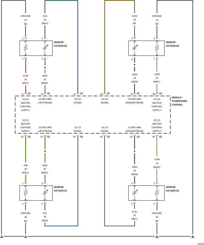 |
For a complete wiring diagram, refer to the Wiring Information.
Theory of Operation
The State of Change (SOC) catalyst monitor uses the signals from both the Upstream and Downstream O2 Sensors to detect aging of the catalyst. Based on the fact that when a catalyst ages, it loses some of its Oxygen Storage Capacity (OSC). As a result, part of the untreated exhaust gases can breakthrough the catalyst and causes the Downstream O2 Sensor to deviate from its neutral (Stoichiometric) position. By observing the activities in the Downstream O2 Sensor signal, the degradation level of catalyst can be detected. In general, the higher the Downstream O2 Sensor SOC value, the more exhaust gas breakthrough and the lower the OSC of the Catalytic Converter.
-
When Monitored:
The monitor will run at between 1400 and 2300 RPM and MAP vacuum between 40 to 70 kPa (15.0 and 21.0 Hg).
-
Set Condition:
If the final State of Change index is within the calibrated fail threshold. Two trip fault. Three good trips to turn off the MIL.
Possible Causes |
|---|
| (K902) O2 RETURN UPSTREAM CIRCUIT SHORTED TO GROUND |
| (K904) O2 RETURN DOWNSTREAM CIRCUIT SHORTED TO GROUND |
| (K902) O2 RETURN UPSTREAM CIRCUIT OPEN |
| (K904) O2 RETURN DOWNSTREAM CIRCUIT OPEN |
| EXHAUST LEAK |
| ENGINE MECHANICAL CONDITION |
| AGING O2 SENSOR |
| CATALYTIC CONVERTER |
Always perform the Pre-Diagnostic Troubleshooting procedure before proceeding. (Refer to 28 - DTC-Based Diagnostics/MODULE, Powertrain Control (PCM) - Standard Procedure).
1. ACTIVE DIAGNOSTIC TROUBLE CODE (DTC)
| NOTE: | A new rear O2 Sensor along with an aging front O2 Sensor may cause the DTC to set. Review the repair history of the vehicle before continuing. |
| NOTE: | If an O2 Sensor DTC set along with the Catalytic Converter Efficiency DTC diagnose the O2 Sensor DTCs before continuing. |
| NOTE: | Check for contaminants that may have damaged the O2 Sensor and Catalytic Converter: contaminated fuel, unapproved silicone, oil and coolant, repair necessary. |
| 1. | Start the engine. |
| 2. | Allow the engine to reach normal operating temperature. |
| 3. | With the scan tool, read DTCs. |
| NOTE: | It may be necessary to drive the vehicle to meet the conditions to set this DTC, try to repeat the conditions in which the fault originally set by reviewing the Freeze Frame data. |
Is the DTC Active or Pending at this time?
Yes
- Go To 2
No
- Perform the INTERMITTENT CONDITION diagnostic procedure. (Refer to 28 - DTC-Based Diagnostics/MODULE, Powertrain Control (PCM) - Standard Procedure).
2. VISUALLY INSPECT CATALYTIC CONVERTER
| 1. | Inspect the Catalytic Converter for the following damage: |
Were any problems found?
Yes
- Replace the Catalytic Converter. Repair the condition that may have caused the failure. (Refer to 11 - Exhaust System/CONVERTER, Catalytic - Removal) .
- Perform the POWERTRAIN VERIFICATION TEST. (Refer to 28 - DTC-Based Diagnostics/MODULE, Powertrain Control (PCM) - Standard Procedure).
No
- Go To 3
3. (K902) O2 SENSOR 1/1 RETURN CIRCUIT VOLTAGE CHECK
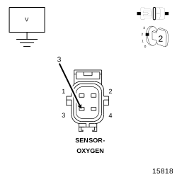 |
| 1. | Turn the ignition off. |
| 2. | Disconnect the O2 Sensor 1/1 harness connector. |
| 3. | Turn the ignition on. |
| 4. | Measure the voltage on the (K902) O2 Sensor 1/1 Return circuit in the O2 Sensor 1/1 harness connector. |
Is the voltage at 2.5 Volts?
Yes
- Go To 4
No
-
Go To 5
4. (K904) O2 SENSOR 1/2 RETURN CIRCUIT VOLTAGE CHECK
|
| 1. | Turn the ignition off. |
| 2. | Disconnect the O2 Sensor 1/2 harness connector. |
| 3. | Turn the ignition on. |
| 4. | Measure the voltage on the (K904) O2 Sensor 1/2 Return circuit in the O2 Sensor 1/2 harness connector. |
Is the voltage at 2.5 Volts?
Yes
- Go To 10
No
-
Go To 7
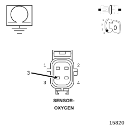
5. (K902) O2 SENSOR 1/1 RETURN CIRCUIT SHORTED TO GROUND
 |
| 1. | Turn the ignition off. |
| 2. | Disconnect the PCM C2 harness connector. |
| 3. | Measure the resistance between ground and the (K902) O2 Sensor 1/1 Return circuit in the O2 Sensor 1/1 harness connector. |
Is the resistance below 100 ohms?
Yes
- Repair the short to ground in the (K902) O2 Sensor 1/1 Return circuit.
- Perform the POWERTRAIN VERIFICATION TEST. (Refer to 28 - DTC-Based Diagnostics/MODULE, Powertrain Control (PCM) - Standard Procedure).
No
-
Go To 6
6. (K902) O2 SENSOR 1/1 RETURN CIRCUIT OPEN
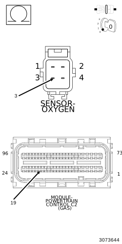 |
| 1. | Measure the resistance of the (K902) O2 Sensor 1/1 Return circuit from the O2 Sensor 1/1 harness connector to the PCM C2 harness connector. |
Is the resistance below 5.0 ohms?
Yes
- Go To 9
No
- Repair the open in the (K902) O2 Return Upstream circuit.
-
Perform the POWERTRAIN VERIFICATION TEST. (Refer to 28 - DTC-Based Diagnostics/MODULE, Powertrain Control (PCM)
- Standard Procedure).
7. (K904) O2 SENSOR 1/2 RETURN CIRCUIT SHORTED TO GROUND
|
| 1. | Turn the ignition off. |
| 2. | Disconnect the O2 Sensor 1/2 harness connector. |
| 3. | Measure the resistance between ground and the (K904) O2 Sensor 1/2 Return circuit in the O2 Sensor 1/2 harness connector. |
Is the resistance below 100 ohms?
Yes
- Repair the short to ground in the (K904) O2 Sensor 1/2 Return circuit.
- Perform the POWERTRAIN VERIFICATION TEST. (Refer to 28 - DTC-Based Diagnostics/MODULE, Powertrain Control (PCM) - Standard Procedure).
No
-
Go To 8
8. (K904) O2 SENSOR 1/2 RETURN CIRCUIT OPEN
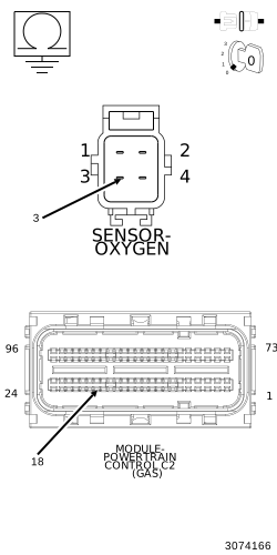 |
| 1. | Measure the resistance of the (K904) O2 Sensor 1/2 Return circuit from the O2 Sensor 1/2 harness connector to the PCM C2 harness connector. |
Is the resistance below 5.0 ohms?
Yes
- Go To 9
No
- Repair the open in the (K904) O2 Sensor 1/2 Return circuit.
-
Perform the POWERTRAIN VERIFICATION TEST. (Refer to 28 - DTC-Based Diagnostics/MODULE, Powertrain Control (PCM)
- Standard Procedure).
9. POWERTRAIN CONTROL MODULE (PCM)
| 1. | Using the wiring diagram/schematic as a guide, inspect the wiring and connectors between the Sensor and the Powertrain Control Module (PCM). |
Were there any problems found?
Yes
- Repair as necessary.
- Perform the POWERTRAIN VERIFICATION TEST. (Refer to 28 - DTC-Based Diagnostics/MODULE, Powertrain Control (PCM) - Standard Procedure).
No
- Replace and program the Powertrain Control Module in accordance with the Service Information. (Refer to 08 - Electrical/8E - Electronic Control Modules/MODULE, Powertrain Control - Removal) .
- Perform the POWERTRAIN VERIFICATION TEST. (Refer to 28 - DTC-Based Diagnostics/MODULE, Powertrain Control (PCM) - Standard Procedure).
10. CHECKING THE EXHAUST SYSTEM FOR LEAKS
| 1. | Turn the ignition off. |
| 2. | Raise the vehicle in accordance with the Service Information. |
The normal operating temperature
of the exhaust system is very high. Never work around or attempt to
service any part of the exhaust system until it has cooled. Special
care should be taken when working near the catalytic converter. The
temperature of the converter rises to a high level after a short period
of engine operating time.
WARNING:
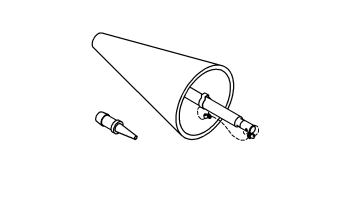
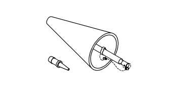
| 3. | Connect Exhaust Cone 8404-EC or Exhaust Cone 8404-EC to Air Pressure Regulator (with hose) W-18-MIL-1146AS. |
The air pressure must not exceed
27.6 kPa (4 psi), otherwise engine damage can occur.
CAUTION:
| 4. | Attach shop air to the air pressure regulator. |
| 5. | Adjust the Air Pressure Regulator to 27.6 kPa (4 psi). |
| 6. | Insert the exhaust cone into the vehicle tail pipe. |
| 7. | If the vehicle is equipped with dual exhaust. Use the Exhaust Cone, Truck 8404-ECT with equipped attached plug, plug one side of the dual exhaust pipe. Pressurize the other as described above. |
| 8. | Apply Mopar® Air Leak Detector PN# 05191804AA (or an equivalent leak finder liquid) to the following areas: |
| 9. | Watch for the liquid/soapy water to bubble. |
| 11. | If a leak is found that matches the above definition, repair or replace the component as necessary. |
| 12. | Once the repair is complete, repeat the procedure to verify that all leaks have been repaired. |
Were any exhaust leaks found?
Yes
- Repair or replace the leaking exhaust parts as necessary.
- Perform the POWERTRAIN VERIFICATION TEST. (Refer to 28 - DTC-Based Diagnostics/MODULE, Powertrain Control (PCM) - Standard Procedure).
No
- Go To 11
11. ENGINE MECHANICAL CONDITION
| 1. | Check the exhaust for excessive smoke caused by an internal problem in the engine. |
Is an engine mechanical condition present?
Yes
- Repair the engine mechanical condition as necessary.
- Perform the POWERTRAIN VERIFICATION TEST. (Refer to 28 - DTC-Based Diagnostics/MODULE, Powertrain Control (PCM) - Standard Procedure).
No
- Go To 12
| 1. | A new Downstream O2 Sensor along with an aging Upstream O2 Sensor may cause the DTC to set. |
| 2. | Review the vehicles repair history. |
Has the Downstream O2 Sensor been replaced without replacing the Upstream O2 Sensor?
Yes
- Replace the front O2 Sensor as necessary. (Refer to 11 - Exhaust System/CONVERTER, Catalytic - Removal) .
- Perform the POWERTRAIN VERIFICATION TEST. (Refer to 28 - DTC-Based Diagnostics/MODULE, Powertrain Control (PCM) - Standard Procedure).
No
- Go To 13
If there are no possible cause remaining, view repair.
Repair
- Replace the Catalytic Converter. (Refer to 11 - Exhaust System/CONVERTER, Catalytic - Removal) .
- Perform the POWERTRAIN VERIFICATION TEST. (Refer to 28 - DTC-Based Diagnostics/MODULE, Powertrain Control (PCM) - Standard Procedure).