For a complete wiring diagram, refer to the Wiring Information.
When Monitored:
Ignition on.
Set Condition:
When the Powertrain Control Module (PCM) recognizes the Auxiliary 5-Volt Supply circuit voltage is varying too much to quickly. One Trip Fault. ETC light is flashing.
Possible Causes
(K856) AUXILIARY 5-VOLT SUPPLY CIRCUIT SHORTED TO GROUND
(K856) AUXILIARY 5-VOLT SUPPLY CIRCUIT SHORTED TO VOLTAGE
Improperly installed aftermarket accessories can cause this DTC to set. Check for any improperly installed aftermarket accessories before continuing with this test.
1.
Start the engine and allow it to idle for at least 60 seconds.
WARNING:
When the engine is operating, do
not stand in direct line with the fan. Do not put your hands near
the pulleys, belts or fan. Do not wear loose clothing. Failure to
follow these instructions may result in possible serious or fatal
injury.
2.
(K856) AUXILIARY 5-VOLT SUPPLY CIRCUIT SHORTED TO GROUND
1.
Turn the ignition off.
2.
Disconnect the PCM C2 harness connector.
3.
Disconnect all the Sensors that share the (K856) Auxiliary 5-Volt Supply circuit.
4.
Disconnect the APP Sensor harness conector.
NOTE:
This code can be caused by the improper installation of after market accessories that may be causing excessive noise on the (K856) 5-Volt Supply circuit.
5.
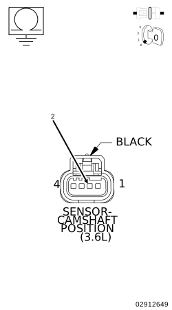
Measure the resistance between ground and the (K856) Auxiliary 5-Volt Supply circuit at the CMP 1/1 Sensor harness connector.
Is the resistance below 100 Ohms?
Yes
Repair the short to ground in the (K856) Auxiliary 5-Volt Supply circuit.
Connect the PCM C2 harness connector and all the previously disconnected Sensors except for the CMP 1/1 Sensor harness connector.
2.
Ignition on, engine not running.
3.
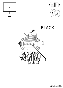
Measure the voltage on the (K856) Auxiliary 5-Volt Supply circuit in the CMP 1/1 Sensor harness connector.
NOTE:
You must Turn the Ignition OFF when disconnecting any of the Sensor harness connectors and Turn the Ignition On to check the voltage readings.
4.
While monitoring the voltage, disconnect each Sensor harness connector that shares the (K856) Auxiliary 5-Volt Supply circuit, one at a time including the APP Sensor harness connector.
Does the voltage increase above 4.5 Volts when disconnecting any of the Sensor harness connectors?
Yes
Verify that there is good pin to terminal contact in the related Sensor and Powertrain Control Module harness connectors. If OK, replace the Sensor that causes the (K856) Auxiliary 5-Volt Supply circuit voltage to increase when disconnected.
Using the wiring diagram/schematic as a guide, inspect the wiring and connectors between the related Sensors and the Powertrain Control Module (PCM).
2.
Look for any chafed, pierced, pinched, or partially broken wires.
3.
Look for broken, bent, pushed out or corroded terminals. Verify that there is good pin to terminal contact in the related Sensor and Powertrain Control Module connectors.
4.
Perform any Technical Service Bulletins that may apply.