Raise the vehicle
in accordance with the Service Information.
WARNING:
The normal operating temperature
of the exhaust system is very high. Never work around or attempt to
service any part of the exhaust system until it has cooled. Special
care should be taken when working near the catalytic converter. The
temperature of the converter rises to a high level after a short period
of engine operating time.
The air pressure must not exceed
27.6 kPa (4 psi), otherwise engine damage can occur.
4.
Attach shop air
to the air pressure regulator.
5.
Adjust the Air
Pressure Regulator to 27.6 kPa (4 psi).
6.
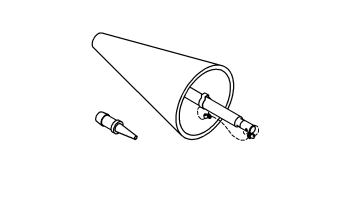
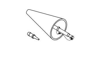
Insert the exhaust
cone into the vehicle tail pipe.
7.
If the vehicle
is equipped with dual exhaust. Use the
Exhaust Cone, Truck 8404-ECT
with equipped
attached plug, plug one side of the dual exhaust pipe. Pressurize
the other as described above.
8.
Apply Mopar® Air
Leak Detector PN 05191804AA (or an equivalent leak finder liquid)
to the following areas:
All welded joints from
the exhaust manifold to 152.4 mm (6 inches) behind the downstream
O2 sensor
O2 sensor seal points
O2 sensor boss welds
Flange/joint connection(s)
Exhaust manifold to
cylinder head connection(s)
EGR solenoid gasket
base and tube seal points (if equipped)
9.
Watch for the Mopar®
Air Leak Detector PN 05191804AA (or the equivalent leak finder liquid)
to bubble.
10.
Use the following
definitions to help determine if system or component repair/replacement
is necessary:
Type 1 Leak is
defined as a leak where very small foam like bubbles 1 mm (0.04 of
an inch) or less appear. Any Type 1 or greater leaks found in welded
joints, O2 sensor seal points or O2 sensor boss welds must be repaired
or the component must be replaced.
Type 2 Leak is
defined as a leak where larger bubbles pea size, 8 mm (0.3 of an inch)
or greater appear. Any Type 2 or greater leaks found in flange or
joint connections, exhaust manifold to cylinder head connections or
EGR gasket and tube seal points must be repaired or the components
must be replaced.
Leak Location
Repair required if
results at 27.6 kPa (4 psi) reveal bubble size:
Welded joints
Type 1, 1 mm (0.04 of an inch) or greater
O2 Sensor
seal points
Type 1,
1 mm (0.04 of an inch) or greater
O2 Sensor
boss welds
Type 1,
1 mm (0.04 of an inch) or greater
Flange /
joint connections
Type 2,
8 mm (0.3 of an inch) or greater
Exhaust
Manifold to cylinder head connections
Type 2,
8 mm (0.3 of an inch) or greater
EGR gasket
and tube seal points
Type 2,
8 mm (0.3 of an inch) or greater
11.
If a leak is found
that matches the above definition, repair or replace the component
as necessary.
12.
Once the repair
is complete, repeat the procedure to verify that all leaks have been
repaired.
Were
any exhaust leaks found?
Yes
Repair or replace the
leaking exhaust parts as necessary.
The fuel system is under a constant
pressure (even with the engine off). Before testing or servicing any
fuel system hose, fitting or line, the fuel system pressure must be
released. Failure to follow these instructions can result in possible
serious or fatal injury.
The fuel system is under a constant pressure even with the engine off. Before testing or servicing any fuel system hose, fitting or line, the fuel system pressure must be released.
The fuel system is under a constant
pressure (even with the engine off). Before testing or servicing any
fuel system hose, fitting or line, the fuel system pressure must be
released. Failure to follow these instructions can result in possible
serious or fatal injury.
1.
Turn the ignition off.
2.
Remove the Fuel Pump Module and inspect the Fuel Inlet Strainer.
For a complete wiring diagram, refer to the Wiring Information.
1.
OXYGEN SENSOR, WIRING, OR CONNECTORS
NOTE:
Diagnose and repair any O2 sensor or rationality DTCs before proceeding with this test.
NOTE:
When performing this procedure as part of another diagnostic process, it may be necessary to repeat this test for all of the oxygen sensors on the vehicle.
1.
Turn the ignition off.
2.
Using the wiring diagram/schematic as a guide, inspect the wiring and connectors between the Oxygen sensor and the PCM.
3.
Look for any chafed, pierced, pinched or partially broken wires.
4.
Look for broken, bent, pushed out or corroded terminals.
5.
Turn the ignition on.
6.
Monitor the scan tool data relative to the sensor and wiggle test the wiring and connectors.
7.
Look for the data to change or for a DTC to set during the wiggle test. If necessary, check each sensor circuit for high resistance or a shorted condition.
Start the engine and allow it to reach normal operating temperature.
WARNING:
When the engine is operating, do
not stand in direct line with the fan. Do not put your hands near
the pulleys, belts or fan. Do not wear loose clothing. Failure to
follow these instructions may result in possible serious or fatal
injury.
2.
With the scan tool, monitor all O2 Sensor voltage readings.
Is the voltage switching between 2.5 and 3.4 Volts for all O2 sensors?
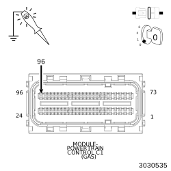
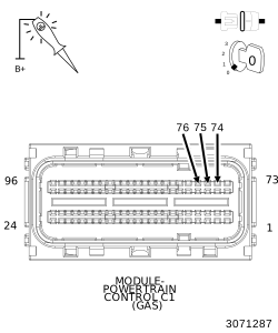
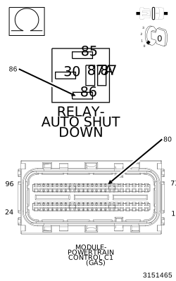
Connect a jumper between ground and the (K51) ASD Relay Control circuit in PCM C1 harness connector (cavity 28) to close the relay.
3.
Turn the ignition on.
4.
Using a 12-volt test light connected to ground, probe the (F342) and (F344) ASD Relay Output circuits at the PCM C1 harness connector (cavities 1, 3 and 5).
Does the test light illuminate brightly for each circuit?
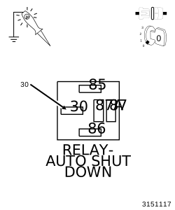
Connect a jumper between cavity 30 and cavity 87 at the ASD Relay connector.
2.
Using a 12-volt test light connected to ground, probe the (F342) and (F344) ASD Relay Output circuits at the PCM C1 harness connector (cavities 1, 3 and 5).
For a complete wiring diagram, refer to the Wiring Information.
Possible Causes
NO START PRE-TEST
POWERTRAIN FUSES OPEN
SECONDARY INDICATORS PRESENT
ENGINE MECHANICAL PROBLEM
FUEL CONTAMINATION
1.
NO START PRE-TEST
NOTE:
The following list of items must be checked before continuing with any no start tests.
1.
The battery must be fully charged and in good condition. A low charged battery may produce invalid test results. If the battery is low, charge the battery and then attempt to start the vehicle by cranking the engine for 15 seconds, three consecutive times. This will allow any DTCs to set that may have been erased due to a dead battery.
Read the PCM DTCs with the scan tool. If any DTCs are present, they must be repaired before continuing with any other No Start diagnostic tests. Perform the appropriate diagnostic procedure.
4.
Inspect all fuses in the TIPM and the Junction Box. If an open fuse(s) is found, check the related circuit(s) for a short to ground or high resistance.
5.
Using a test light, check the Powers and Ground to the PCM. The test light must illuminate brightly as if jumpered across a battery.
6.
Attempt to communicate with the Instrument Cluster and VTSS. If you are unable to establish communications perform the appropriate diagnostic procedures.
7.
The Wireless Ignition Node (WIN) must be operating properly. Check for proper communication with the scan tool and check for DTCs that may be stored in the WCINM. Repair the DTC(s) before continuing.
8.
If no DTCs are found, using the scan tool, select Clear PCM (BATT Disconnect).
9.
Crank the engine several times. Using the scan tool, read DTCs. If a DTC is present perform the DTC diagnostics before continuing.
Verify that the Fuel tank is not empty before continuing.
2.
Follow the diagnostics for Checking Fuel Delivery inf this section.
Was the No Start condition solved after following the above diagnostic test?
Yes
Test Complete.
No
Check for contamination/water in the fuel. Make sure the fuel being used in this vehicle meets manufactures Fuel Requirement, refer to the service manual.
For a complete wiring diagram, refer to the Wiring Information.
Possible Causes
ETC STARTER INHIBIT
ETC STARTER INHIBIT
NOTE:
This ETC equipped engine will try to relearn ETC position when the key is left in the on position for an extended period of time and will not allow the starter to crank during this procedure. This procedure can take up to 2.5 seconds.
1.
To verify the cause of the no crank condition or delayed crank use the scan tool and read the ETC Starter Inhibit mileage.
2.
The controller will store the mileage at which the no start condition occurred because of the ETC testing procedure.
3.
This is considered normal operation for a vehicle equipped with an Electronic Throttle Control System and no repairs are necessary.
Is a mileage stored under the ETC Starter Inhibit?
Yes
Test Complete.
No
Refer to the appropriate diagnostic procedure for further assistance if any other DTCs are set.
For a complete wiring diagram, refer to the Wiring Information.
WARNING:
Follow these safety precautions to reduce the risk of fire and possible serious or fatal injury when performing this test procedure.
Fuel or fuel vapors are highly flammable. A fire could occur if an ignition source is present. Do not expose the fuel or the test equipment used in this procedure to open flames or sparks.
Inhalation of fuel vapors could lead to disorientation and personal injury. Keep the service area well ventilated, or perform this test procedure in an area where there is a building exhaust removal system.
Relieve fuel system pressure before servicing fuel system components.
Use extreme caution when connecting and disconnecting fuel lines.
Considerable fuel leakage may occur when servicing the fuel system. Wear protective eyewear and clothing to protect from fuel splash, and take suitable fuel containment measures.
Wrap a shop towel around the fuel pressure gauge connection to absorb fuel leakage that occurs when connecting the test equipment. Place the towel in an approved container when complete.
Never store fuel in an open container due to the possibility of fire or explosion. Have a dry chemical (Class B) fire extinguisher nearby.
1.
CHECK FUEL DELIVERY
SYSTEM FOR LEAKS AND DAMAGE
WARNING:
The fuel system is under a constant pressure (even with the engine off). Before testing or servicing any fuel system hose, fitting, or line, the fuel system pressure must be released. Failure to follow these instructions can result in possible serious or fatal injury.
1.
Visually and physically
inspect the fuel delivery system for external leaks and damage.
2.
INSTALL APPROPRIATE
FUEL LINE ADAPTERS / FITTING FROM THE GAS AND DIESEL FUEL PRESSURE/DECAY
TESTER 8978A
1.
Turn the ignition
off.
WARNING:
The fuel system is under a constant pressure (even with the engine off). Before testing or servicing any fuel system hose, fitting, or line, the fuel system pressure must be released. Failure to follow these instructions can result in possible serious or fatal injury.
2.
Disconnect the
frame rail fuel supply line connector between the fuel supply line
and the fuel rail.
3.
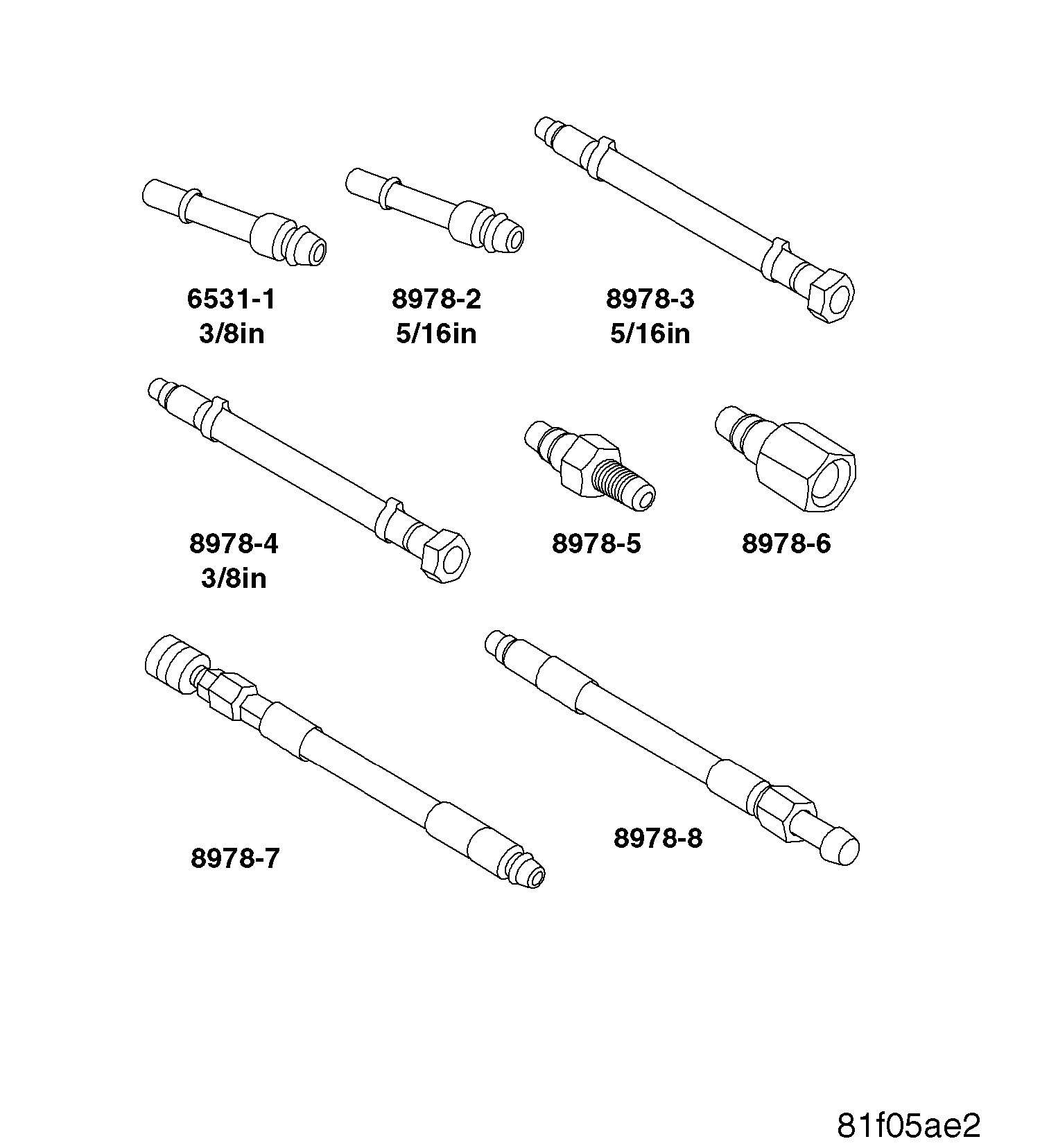
Install the appropriate
Fuel Line Adapters / Fitting from the Gas and Diesel
Decay Tool, Fuel 8978A
.
The fuel system is under a constant pressure (even with the engine off). Before testing or servicing any fuel system hose, fitting, or line, the fuel system pressure must be released. Failure to follow these instructions can result in possible serious or fatal injury.
1.
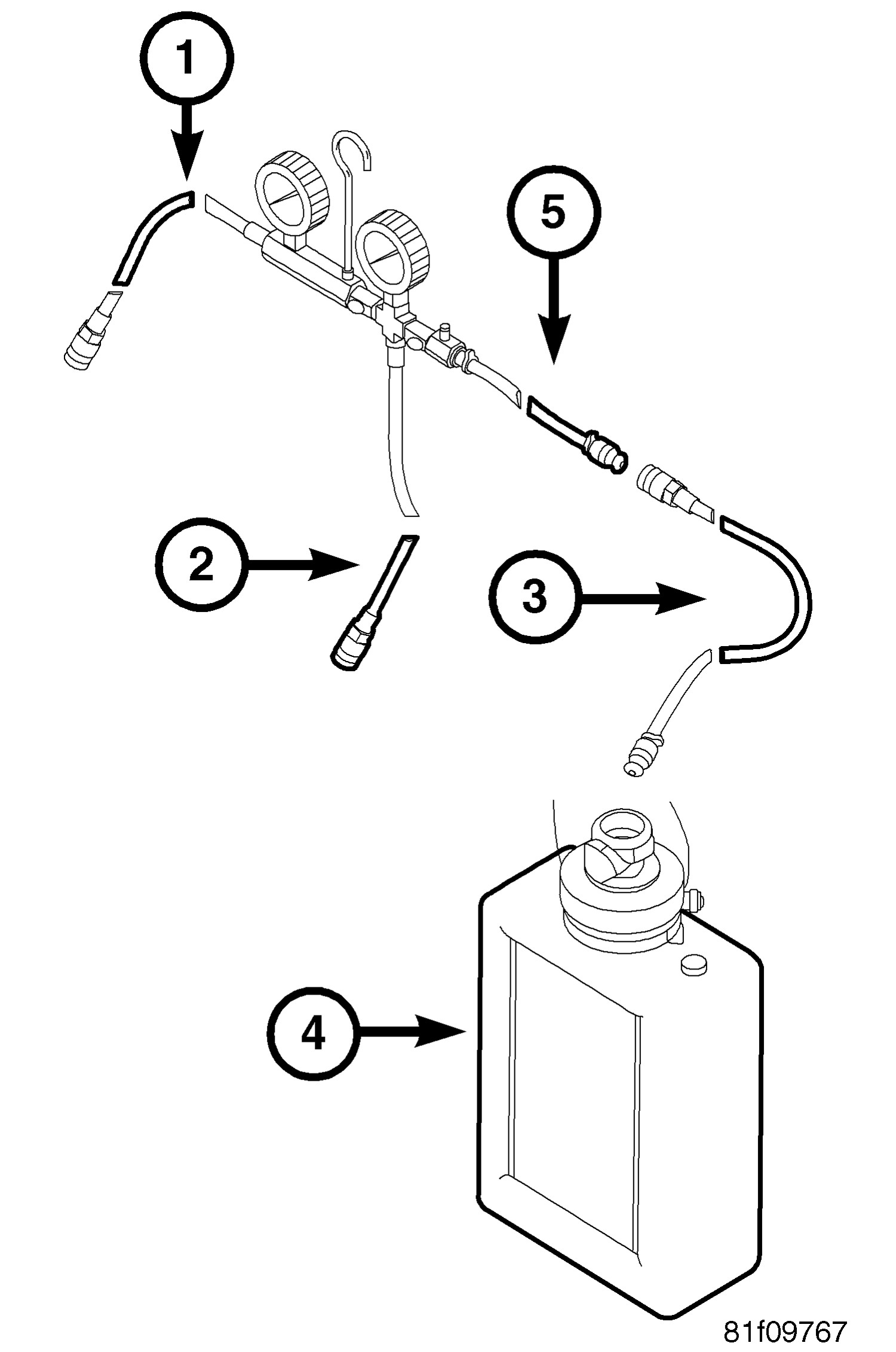
Connect the Gas
and Diesel
Decay Tool, Fuel 8978A
, Fuel Inlet Hose
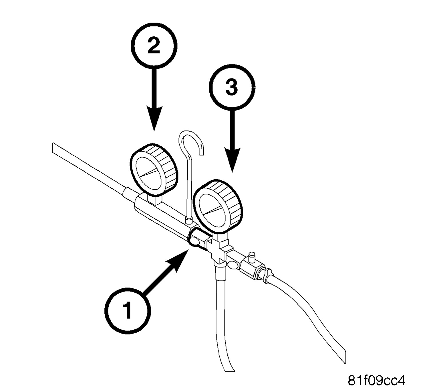
(1) and Fuel Outlet Hose (2) to the Fuel Line Adapters / Fitting.
2.
Connect special
tool Drain Extension Hose 535680 (3) to the Fuel Pressure Gauge Assembly
Drain Hose (5).
To reduce the risk of fire and possible serious or fatal injury, place Reservoir Assembly 534960 (4) on the floor and out of the way so that it is not a trip hazard.
The fuel system is under a constant pressure (even with the engine off). Before testing or servicing any fuel system hose, fitting, or line, the fuel system pressure must be released. Failure to follow these instructions can result in possible serious or fatal injury.
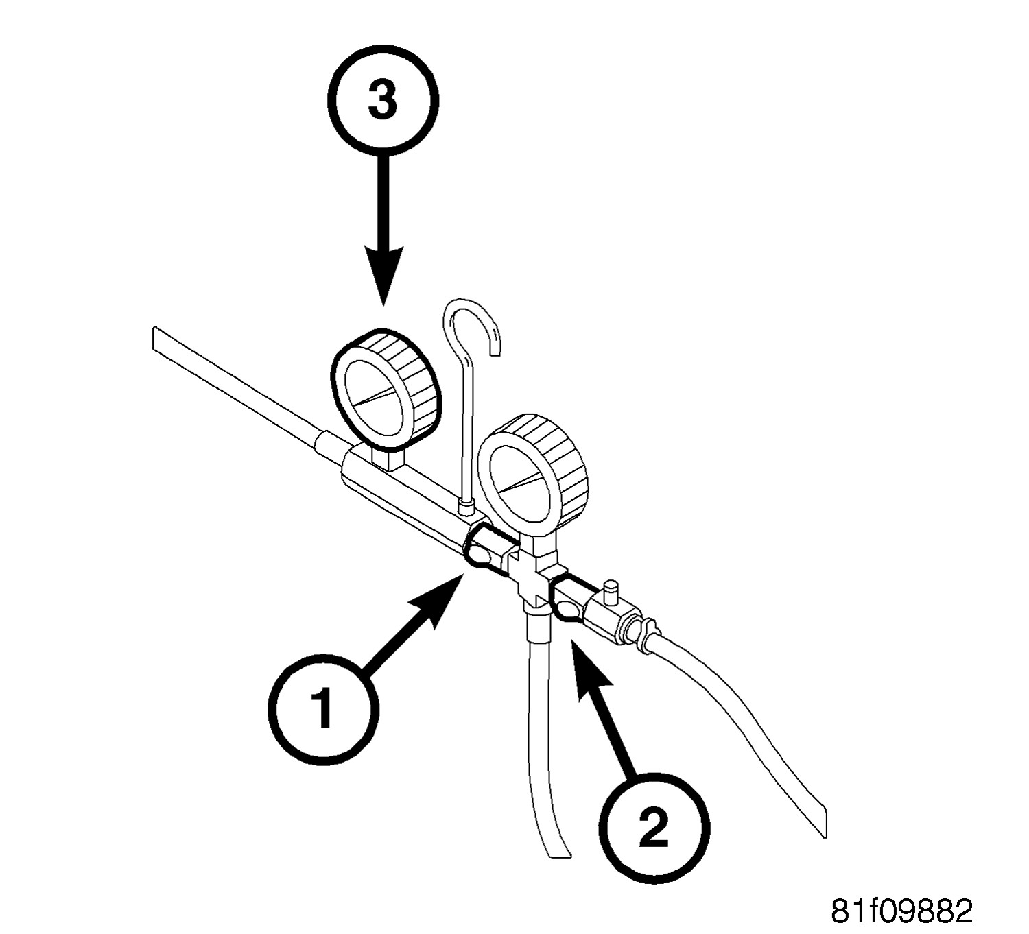
1.
Perform the
following procedure to purge air from the system:
Open the Fuel System
Isolation Valve (1).
Close the Flow Test
Valve (2).
Ignition on, engine
not running.
With the scan tool,
actuate the fuel pump.
Open the Flow Test
Valve (1) for 10 seconds, then close the Valve.
CAUTION: Stop All Actuations.
Turn the ignition off.
Disconnect, empty and
then reconnect the Reservoir Assembly.
2.
Turn the ignition
on, wait five seconds, turn the ignition off and then wait one minute
before proceeding.
3.
Read the Fuel Pressure
Gauge (3) and record the reading. Fuel pressure specification is 407
kPa +/- 34 kPa (59 psi +/- 5 psi).
The fuel system is under a constant pressure (even with the engine off). Before testing or servicing any fuel system hose, fitting, or line, the fuel system pressure must be released. Failure to follow these instructions can result in possible serious or fatal injury.
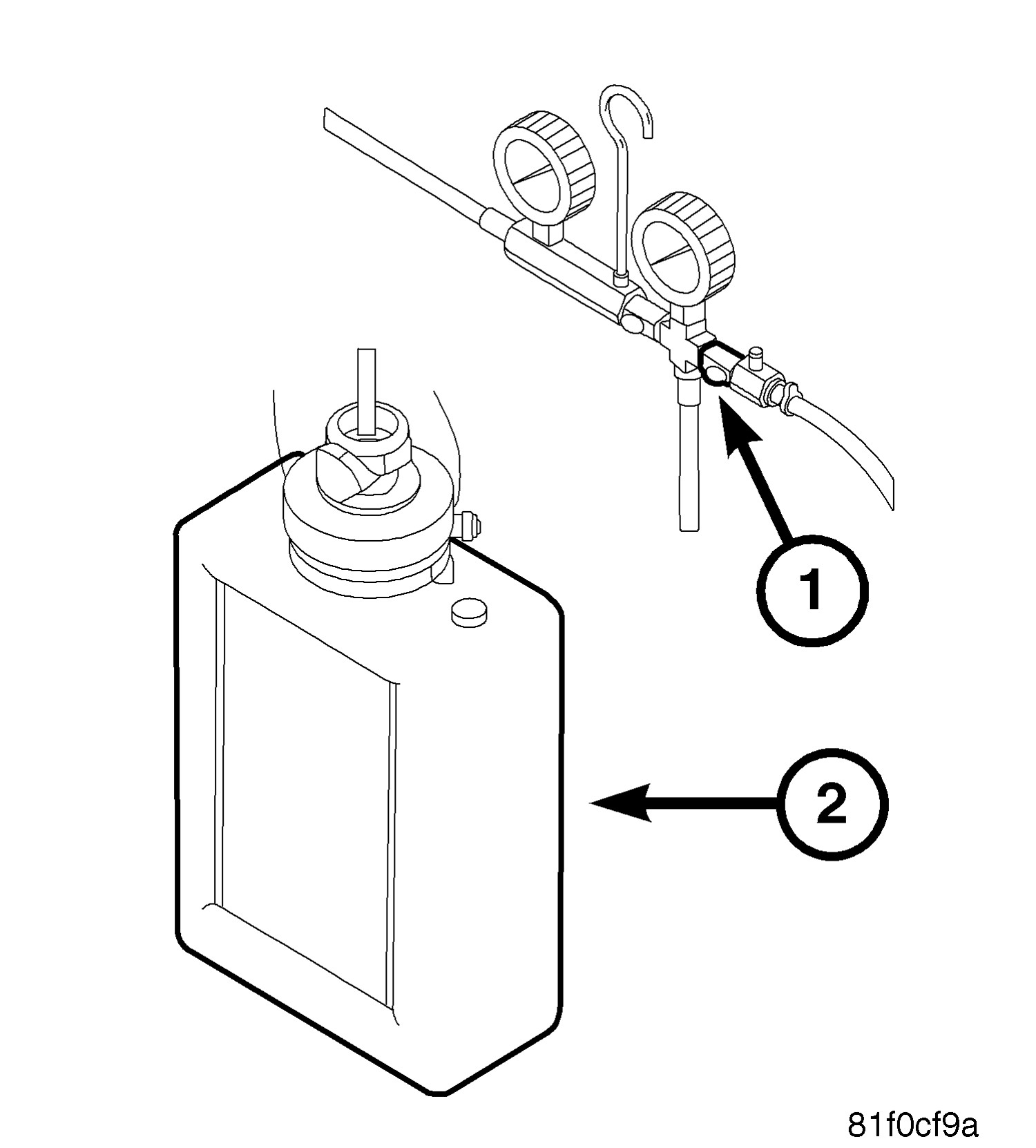
1.
Ignition on, engine
not running.
2.
With the scan tool,
actuate the fuel pump.
3.
Open the Flow Test
Valve (1) for 20 seconds, then close the Valve.
CAUTION:
Stop All Actuations.
4.
Turn the ignition
off.
5.
Measure the amount
of fuel in the Reservoir Assembly (2). The fuel output specification
is ml/s × 20 seconds = fuel flow in ml.
FUEL FLOW
ENGINE
ml/s
ml per 20 Seconds
4 Cylinder
and 6 Cylinder
20.8333A
417
8 Cylinder
38.88889
778
Does
the amount of fuel in the reservoir meet or exceed the specification?
For a complete wiring diagram, refer to the Wiring Information.
Possible Causes
FUEL DELIVERY SYSTEM LEAKING OR DAMAGED
FUEL PUMP MODULE
FUEL INJECTOR(S)
WARNING:
Follow these safety precautions to reduce the risk of fire and serious possible serious or fatal injury when performing this test procedure.
Fuel or fuel vapors are highly flammable. A fire could occur if an ignition source is present. Do not expose the fuel or the test equipment used in this procedure to open flames or sparks.
Inhalation of fuel vapors could lead to disorientation and personal injury. Keep the service area well ventilated, or perform this test procedure in an area where there is a building exhaust removal system.
Relieve fuel system pressure before servicing fuel system components.
Use extreme caution when connecting and disconnecting fuel lines.
Considerable fuel leakage may occur when servicing the fuel system. Wear protective eye wear and clothing to protect from fuel splash, and take suitable fuel containment measures.
Wrap a shop towel around the fuel pressure gauge connection to absorb fuel leakage that occurs when connecting the test equipment. Place the towel in an approved container when complete.
Never store fuel in an open container due to the possibility of fire or explosion. Have a dry chemical (Class B) fire extinguisher nearby.
1.
CHECK FUEL DELIVERY SYSTEM FOR LEAKS AND DAMAGE
WARNING:
The fuel system is under a constant pressure (even with the engine off). Before testing or servicing any fuel system hose, fitting, or line, the fuel system pressure must be released. Failure to follow these instructions can result in possible serious or fatal injury.
1.
Visually and physically inspect the fuel delivery system for external leaks and damage.
2.
INSTALL APPROPRIATE FUEL LINE ADAPTERS / FITTING FROM GAS AND DIESEL FUEL PRESSURE/DECAY TESTER 8978A
1.
Turn the ignition off.
WARNING:
The fuel system is under a constant pressure (even with the engine off). Before testing or servicing any fuel system hose, fitting, or line, the fuel system pressure must be released. Failure to follow these instructions can result in possible serious or fatal injury.
2.
Disconnect the frame rail fuel supply line connector between the fuel supply line and the fuel rail.
3.
Install the appropriate Fuel Line Adapters / Fitting from Gas and Diesel
Decay Tool, Fuel 8978A
.
The fuel system is under a constant pressure (even with the engine off). Before testing or servicing any fuel system hose, fitting, or line, the fuel system pressure must be released. Failure to follow these instructions can result in possible serious or fatal injury.
Connect Drain Extension Hose 535680 (3) to the Fuel Pressure Gauge Assembly Drain Hose (5).
3.
Connect the Reservoir Assembly 534960 (4) to the Drain Extension Hose 535680 (3).
WARNING:
To reduce the risk of fire and serious possible serious or fatal injury, place Reservoir Assembly 534960 (4) on the floor and out of the way so that it is not a trip hazard.
The fuel system is under a constant pressure (even with the engine off). Before testing or servicing any fuel system hose, fitting, or line, the fuel system pressure must be released. Failure to follow these instructions can result in possible serious or fatal injury.
1.
Perform the following procedure to purge air from the system:
Open the Fuel System Isolation Valve (1).
Close the Flow Test Valve (2).
Ignition on, engine not running.
With the scan tool, actuate the fuel pump.
Open the Flow Test Valve (1) for 10 seconds, then close the Valve.
CAUTION: Stop All Actuations.
Turn the ignition off.
Disconnect, empty and then reconnect the Reservoir Assembly.
2.
Turn the ignition on, wait five seconds, turn the ignition off and then wait 1 minute before proceeding.
3.
Read the Fuel Pressure Gauge (3) and record the reading. Fuel pressure specification is 407 KPa +/- 34 KPa (59 psi +/- 5 psi).
Perform the Checking The Fuel Delivery System diagnostic procedure as directed.
5.
CHECK FUEL DELIVERY SYSTEM FOR LEAK DOWN
WARNING:
The fuel system is under a constant pressure (even with the engine off). Before testing or servicing any fuel system hose, fitting, or line, the fuel system pressure must be released. Failure to follow these instructions can result in possible serious or fatal injury.
1.
Close the Fuel System Isolation Valve (1) and then wait five minutes before proceeding.
2.
Read the Fuel Inlet (2) and Fuel Outlet (3) Pressure Gauges. The pressure should not drop more than 10 psi on either gauge.
For a complete wiring diagram, refer to the Wiring Information.
Possible Causes
FUEL CONTAMINATION
RESTRICTED FUEL SUPPLY LINE
FUEL PUMP INLET STRAINER PLUGGED
FUEL PUMP MODULE
FUEL INJECTOR(S)
1.
CHECKING FUEL PRESSURE
WARNING:
The fuel system is under a constant
pressure (even with the engine off). Before testing or servicing any
fuel system hose, fitting or line, the fuel system pressure must be
released. Failure to follow these instructions can result in possible
serious or fatal injury.
The fuel system is under a constant
pressure (even with the engine off). Before testing or servicing any
fuel system hose, fitting or line, the fuel system pressure must be
released. Failure to follow these instructions can result in possible
serious or fatal injury.
The fuel system is under a constant
pressure (even with the engine off). Before testing or servicing any
fuel system hose, fitting or line, the fuel system pressure must be
released. Failure to follow these instructions can result in possible
serious or fatal injury.
1.
Turn the ignition off.
2.
Remove the Fuel Pump Module and inspect the Fuel Inlet Strainer.
Before continuing visually and physically inspect the fuel delivery system for external leaks or damage. Repair/replace as necessary.
WARNING:
The fuel system is under a constant
pressure (even with the engine off). Before testing or servicing any
fuel system hose, fitting or line, the fuel system pressure must be
released. Failure to follow these instructions can result in possible
serious or fatal injury.
If directed here by another test, return to that test. Otherwise, test complete.
NO CRANK CONDITION
NO CRANK CONDITION
For a complete wiring diagram, refer to the Wiring Information.
Possible Causes
MECHANICAL CONDITION
STARTER RELAY
BATTERY CIRCUIT RESISTANCE
TOO HIGH
FUSED B+ CIRCUIT OPEN
STARTER RELAY OUTPUT
CIRCUIT OPEN
STARTER RELAY CONTROL
CIRCUIT OPEN
TRANSMISSION RANGE
SENSOR
STARTER
TOTALLY
INTEGRATED POWER MODULE (TIPM)
POWERTRAIN CONTROL
MODULE (PCM)
1.
MECHANICAL CONDITION
NOTE:
Inspect all fuses and replace as necessary. If a fuse is open check the circuit for a short to ground.
NOTE:
Check the BCM for any starter relay DTCs and diagnose before continuing.
NOTE:
Install a known good Starter relay and see if the vehicle will start.
NOTE:
An external Radio-Frequency Identification (RFID) key (and/or pass/radio key), such as one used to gain access to a 24 hour gym, can cause a DTC to set and create a no start condition. Inspect the customer's key chain for any type of RFID key. If one is not found, question the customer to see if a spare key chain has this RFID key on it or if it was removed from the original key chain before the vehicle was released for service. If a RFID key is present, remove the ignition key from the vehicle and remove the RFID key from the key chain. Turn the ignition on a minimum for one hour, and then attempt to start the vehicle. If the vehicle does not start, continue with the diagnostic test.
NOTE:
Verify the key being used is the proper key for this vehicle and a blank key. If the key being programmed is not blank (one that has been programmed for another vehicle) this fault will set.
NOTE:
Verify the battery is fully charged and capable of passing a load test before continuing.
WARNING:
Make sure the battery is disconnected, then wait two minutes before proceeding. Failure to do so may result in possible serious or fatal injury.
1.
Turn the engine over by hand to make sure the engine is not seized.
Move the Gear selector through all gear positions, from Park to 1st and back.
4.
While moving the gear selector through each gear, measure the resistance between ground and the TRS (T41) Sense (P/N Position Switch Sense) circuit at the TRS connector.
NOTE:
The circuit is grounded in Park and Neutral and open in the other positions.
Did the resistance change from above 100 kOhms (open) to below 10.0 Ohms (grounded) ?
The Parking Brake must be on and the Transmission must be in park for a vehicle equipped with an automatic transmission.
WARNING:
When the engine is operating, do
not stand in direct line with the fan. Do not put your hands near
the pulleys, belts or fan. Do not wear loose clothing. Failure to
follow these instructions may result in possible serious or fatal
injury.
1.
Turn ignition off.
2.
Disconnect the Starter Solenoid harness connector.
NOTE:
The Stater Solenoid harness connector must remain disconnected at this time.
3.
Have an assistant turn the ignition key to the CRANK position.
4.
Using a 12-Volt test light connected ground, probe the (T750) Stater Relay Output circuit at the Starter Solenoid harness connector while the ignition key is in the CRANK position.
Does the test light illuminate brightly?
Yes
Replace the Starter in accordance with the service information.
Disconnect the Starter Solenoid harness connector.
2.
Measure the resistance of the (T750) Starter Control Output circuit between the Starter Solenoid harness connector and the Starter Relay (terminal 87).
If the U0100 DTC is present in any other modules, diagnose that DTC before proceeding with this procedure.
NOTE:
The scan tool and cable must be operating properly for the results of this test to be valid.
1.
Turn the ignition off.
2.
Disconnect the PCM C1 harness connector.
NOTE:
When checking circuits at the Powertrain Control Module (PCM), be careful not to damage or distort the connector terminals. Improper measurement technique could result in poor pin to terminal contact.
3.
Using a 12-Volt test light connected to ground, probe the (A902) Fused B+ circuit in the PCM C1 harness connector.
NOTE:
The test light should be illuminated and bright. Compare the brightness to that of a direct connection to the battery.
Check the Battery supply to the ASD Relay. Check the fuses. If the battery supply and fuses are good, replace the PDC in accordance with the service information.
Check for contamination/water
in the fuel. Make sure the fuel being used in this vehicle meets OEM
Fuel Requirement, perform the appropriate service procedure.
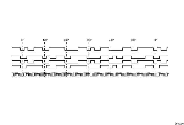
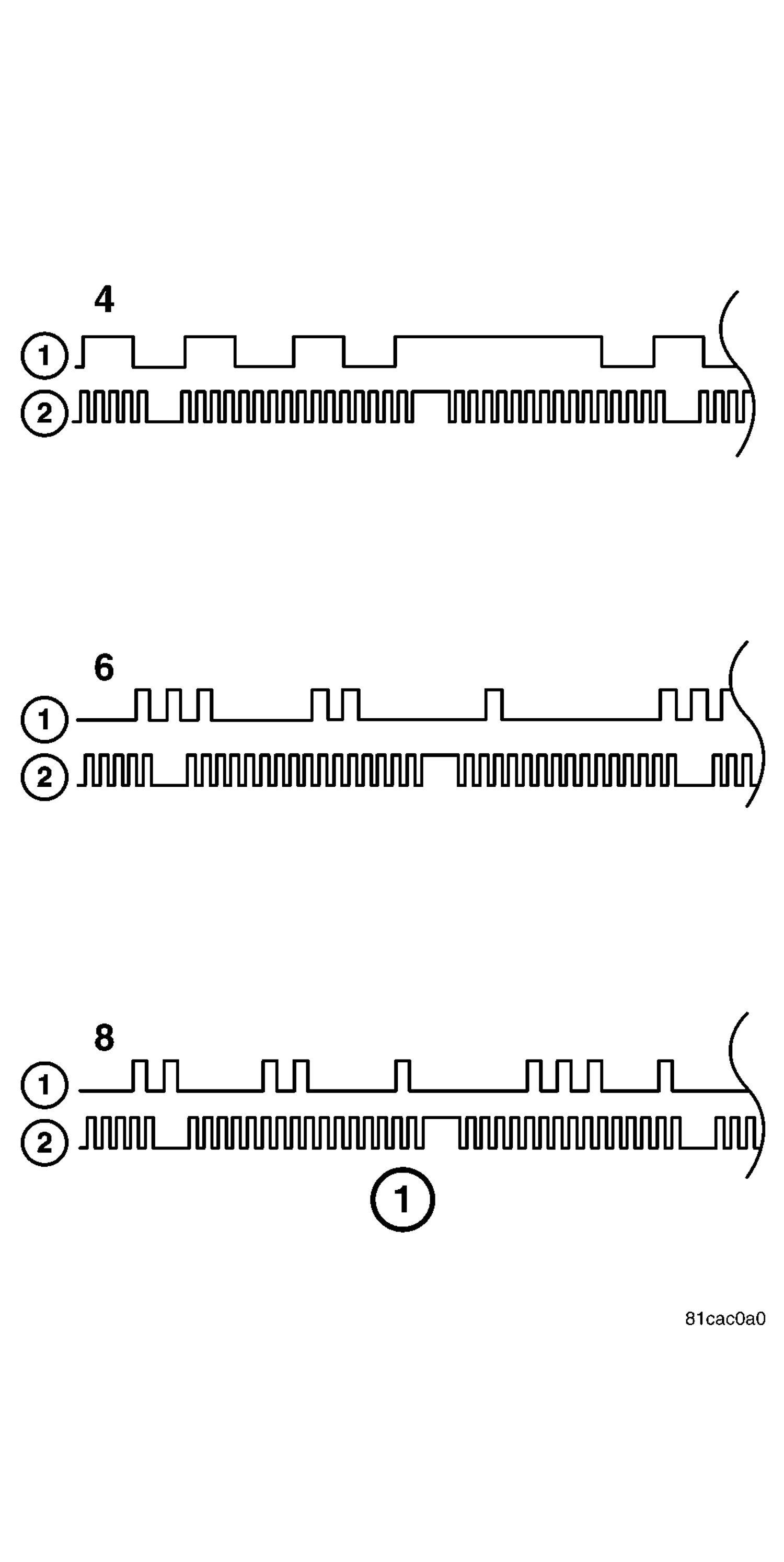
Figure 1 is a depiction
of typical scope patterns of the Cam (1) and Crank (2) sensors for
4, 6, and 8 cylinder engines. The square wave patterns are uniform
and are identical to one another. The patterns must be evenly spread
apart and at the same height. The larger gap pattern (signature) after
the shorter wave forms are used for cylinder identification (Crank
signal) and the distance between the series of slots (trigger) on
the camshaft pulley (cam signal). Any variation of the pattern will
indicate an issue with the sensor, wiring, or trigger (target) wheel.
CAUTION:
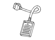
Do not probe the PCM harness connectors. Probing the PCM harness connectors will damage the PCM terminals resulting in poor terminal to pin connection. Install the PCM Pinout Box along with the Adapter to perform the diagnosis.
3.
With a lab scope,
probe the CMP Signal circuit in the appropriate terminal of the PCM
Pinout Box
Kit, NGC, 38 Position 8815A
.
WARNING:
When the engine is operating, do
not stand in direct line with the fan. Do not put your hands near
the pulleys, belts or fan. Do not wear loose clothing. Failure to
follow these instructions may result in possible serious or fatal
injury.
4.
Start and allow
the engine to run.
5.
Observe the lab
scope screen.
6.
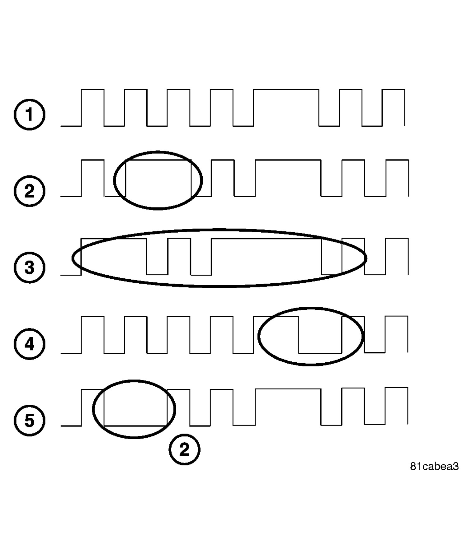
Compare the scope
pattern with the ones in Figure 2.
7.
1. Pattern indicates
a clean (good) square wave form that is identical to what the cam
and crank should be. The square wave patterns are uniformed and are
identical to one another.
8.
2. Two pulses
joined together in the same spot on target. Indicates damage to the
target (trigger) on the flex plate or broke tooth, runout in the target
or large air gap between the sensor and the target wheel.
9.
3. Wide air
gap or intermittent connection.
10.
4. Early signature,
predominately at high speed. Large air gap between the sensor and
the target wheel.
11.
5. Missed pulse.
Possible burr or light damage to target or incorrect lateral position
of the crank sensor to target (trigger).
NOTE:
If any of the above
(except pattern 1) is displayed on the lab scope repair as necessary.
Was
the square wave found to match any of the above except pattern 1?
Figure 1 is a depiction
of typical scope patterns of the Cam (1) and Crank (2) sensors for
4, 6, and 8 cylinder engines. The square wave patterns are uniform
and are identical to one another. The patterns must be evenly spread
apart and at the same height. The larger gap pattern (signature) after
the shorter wave forms are used for cylinder identification (Crank
signal) and the distance between the series of slots (trigger) on
the camshaft pulley (cam signal). Any variation of the pattern will
indicate an issue with the sensor, wiring, and trigger (target) wheel.
CAUTION:
Do not probe the PCM harness connectors. Probing the PCM harness connectors will damage the PCM terminals resulting in poor terminal to pin connection. Install the PCM Pinout Box along with the Adapter to perform the diagnosis.
3.
With a lab scope,
probe the CKP Signal circuit in the appropriate terminal of the PCM
Pinout Box
Kit, NGC, 38 Position 8815A
.
WARNING:
When the engine is operating, do
not stand in direct line with the fan. Do not put your hands near
the pulleys, belts or fan. Do not wear loose clothing. Failure to
follow these instructions may result in possible serious or fatal
injury.
4.
Start and allow
the engine to run.
5.
Observe the lab
scope screen.
6.
Compare the scope
pattern with the ones in Figure 2.
7.
1. Pattern indicates
a clean (good) square wave form that is identical to what the cam
and crank should be. The square wave patterns are uniformed and are
identical to one another.
8.
2. Two pulses
joined together in the same spot on target. Indicates damage to the
target (trigger) on the flex plate or broke tooth, runout in the target
or large air gap between the sensor and the target wheel.
9.
3. Wide air
gap or intermittent connection.
10.
4. Early signature,
predominately at high speed. Large air gap between the sensor and
the target wheel.
11.
5. Missed pulse.
Possible burr or light damage to target or incorrect lateral position
of the crank sensor to target (trigger).
NOTE:
If any of the above
(except pattern 1) is displayed on the lab scope repair as necessary.
Was
the square wave found to match any of the above except pattern 1?