SWITCH, Multifunction, Right
DESCRIPTION
DESCRIPTION
 |
The right (wiper) multi-function switch is located on the right
side of the steering column, just below the steering wheel. This switch
is the primary control for the front and rear wiper and washer systems.
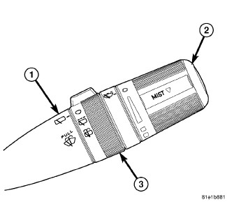
The only visible components of the switch are the control stalk (1),
control knob (2) and control sleeve (3) that extend through the steering
column shrouds on the right side of the column. The remainder of the
switch including its mounting provisions and electrical connection
are concealed beneath the shrouds.
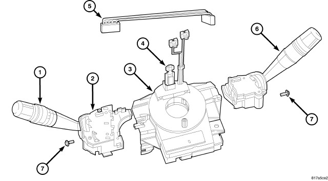 |
The switch housing and controls (6) are constructed of molded black plastic. Each of the switch controls has white International Control and Display Symbol graphics applied to it, which clearly identify its many functions. A single screw (7) through a mounting tab integral to the back of the switch housing, and a slide tab integral to the bottom of the switch housing secure the switch to the mounting bracket integral to the clockspring (3). A single connector receptacle containing seven terminal pins is integral to the inboard end of the switch housing and is connected by a jumper wire harness (5) directly to the Steering Control Module (SCM), which is internal to the housing (2) of the left multi-function switch (1).
The right (wiper) multi-function switch provides the vehicle operator with a control interface for the following wiper and washer system functions:
- Continuous Front Wipers - The right multi-function switch control knob provides detent switching for two continuous front wipe modes, low speed or high speed.
- Intermittent Front Wipers - The right multi-function switch control knob provides detent switching for the intermittent front wipe mode with five minor detent delay interval positions.
- Front Wiper Mist Mode - The right multi-function switch control stalk includes momentary switching of the front wiper motor low speed circuit to provide a mist mode features (sometimes referred to as pulse wipe), which allows the vehicle operator to momentarily operate the front wipers for one or more complete cycles.
- Front Washer Mode - The right multi-function switch control stalk provides momentary switching for control of the front washer system operation.
- Intermittent Rear Wipe Mode - The right multi-function switch control sleeve provides detent switching for a single fixed interval intermittent rear wiper mode.
- Rear Washer Mode - The right multi-function switch control sleeve provides two momentary switch positions for control of rear washer system operation.
The right multi-function switch cannot be adjusted or repaired. If any function of the switch is ineffective, or if the switch is damaged, the entire switch unit must be replaced. The clockspring (with the multi-function switch mounting bracket), the left multi-function switch (with the SCM), the right multi-function switch and the jumper wire harness are each available for separate service replacement.
OPERATION
OPERATION
The right (wiper) multi-function switch uses a combination of resistor multiplexing and conventional analog switching to control the many functions and features it provides. The switch receives a clean ground from the Steering Control Module (SCM), then provides resistor multiplexed and conventional analog return outputs to the SCM to indicate the selected switch positions. The SCM then sends electronic switch status messages over a Local Interface Network (LIN) data bus to the ElectroMechanical Instrument Cluster (EMIC) (also known as the Cab Compartment Node/CCN), and the EMIC relays electronic wiper and washer switch request messages over the Controller Area Network (CAN) data bus to other electronic modules in the vehicle.
If the SCM detects no inputs from the right multi-function switch, it transmits an electronic Signal Not Available (SNA) status message over the LIN data bus. The SNA status signals the EMIC to request other electronic modules to implement a fail-safe mode of operation for the front and rear wiper systems. The fail-safe mode will maintain the last selected front and rear wiper system operation for the remainder of the current ignition cycle, after which both wiper systems will default to OFF.
The right multi-function switch as well as the hard wired inputs and outputs of the switch may be diagnosed using conventional diagnostic tools and procedures. Refer to the appropriate wiring information. However, the most reliable, efficient and accurate means to diagnose this component requires the use of a diagnostic scan tool. Refer to the appropriate diagnostic information.
Following are descriptions of how the right multi-function switch is operated to control the many front and rear wiper and washer system functions and features it provides:
- Front Wiper Control - The control knob on the end of the right multi-function switch control stalk is rotated to one of the two continuous wiper detents, to one of five intermittent wiper detents, or to the OFF position to select the front wiper mode. The SCM reads the input from the right multi-function switch and sends electronic wiper switch status messages over the LIN data bus to the EMIC, which relays an electronic wiper switch request message over the CAN data bus to other electronic modules in the vehicle.
- Front Wiper Mist Mode - The front wiper mist mode is requested when the right multi-function switch control stalk is depressed downward towards the floor to a momentary MIST position. The front wiper motor will continue to operate, one complete cycle at a time, for as long as the control stalk is held in this position. The SCM reads the resistor multiplexed input from the right multi-function switch and sends an electronic wiper switch status message over the LIN data bus to the EMIC, which relays an electronic wiper switch request message over the CAN data bus to other electronic modules in the vehicle.
- Front Washer Control - The right multi-function switch control stalk is pulled rearward towards the steering wheel to a momentary WASH position to activate the washer pump/motor in the front washer mode. The washer pump/motor will continue to operate for as long as the control stalk is held in this position. The SCM reads the resistor multiplexed input from the right multi-function switch and sends an electronic washer switch status message over the LIN data bus to the EMIC, which relays an electronic washer switch request message over the CAN data bus to other electronic modules in the vehicle.
- Rear Wiper Control - The rear wiper mode is selected when the right multi-function switch control sleeve is rotated to the fixed interval intermittent rear wipe detent position, or the OFF detent position. The SCM reads the input from the right multi-function switch and sends an electronic wiper switch status message over the LIN data bus to the EMIC, which relays an electronic wiper switch request message over the CAN data bus to other electronic modules in the vehicle.
- Rear Washer Control - The right multi-function switch control sleeve is rotated to one of two momentary WASH positions, either fully forward or fully rearward, to activate the washer pump/motor in the rear washer mode. The washer pump/motor will continue to operate in the rear washer mode until the control sleeve is released. The SCM reads the input from the right multi-function switch and sends an electronic washer switch status message over the LIN data bus to the EMIC, which relays an electronic washer switch request message over the CAN data bus to other electronic modules in the vehicle.
DIAGNOSIS AND TESTING - RIGHT MULTI-FUNCTION SWITCH
DIAGNOSIS AND TESTING - RIGHT MULTI-FUNCTION SWITCH
To avoid serious or fatal injury on vehicles equipped with airbags, disable the Supplemental Restraint System (SRS) before attempting any steering wheel, steering column, airbag, seat belt tensioner, impact sensor or instrument panel component diagnosis or service. Disconnect and isolate the battery negative (ground) cable, then wait two minutes for the system capacitor to discharge before performing further diagnosis or service. This is the only sure way to disable the SRS. Failure to take the proper precautions could result in accidental airbag deployment.
WARNING:
 |
The right multi-function switch as well as the hard wired inputs and outputs of the switch may be diagnosed using conventional diagnostic tools and procedures. Refer to the appropriate wiring information.
However, conventional diagnostic methods will not prove conclusive in the diagnosis of the Steering Control Module (SCM) or the electronic controls or communication between other modules and devices that provide some features of the front and rear wiper and washer systems. The most reliable, efficient and accurate means to diagnose the SCM or the electronic controls and communication related to SCM operation requires the use of a diagnostic scan tool. Refer to the appropriate diagnostic information.
- Remove the right multi-function switch from the integral mounting bracket on the right side of the clockspring. (Refer to 08 - Electrical/8R - Wipers/Washers/SWITCH, Multifunction - Removal) .
-
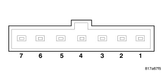
Using an ohmmeter,
test the resistance between the terminals of the switch as shown in
the three Function Tests tables. For all functions except those of
the control stalk the values should be either less than 100 ohms (switch
CLOSED) or greater than 1 megohm (switch OPEN).
CONTROL STALK FUNCTION TESTS
FUNCTION
PINS
RESISTANCE
1
7
Front Wash
X
X
10000 Ohms
Front Mist
X
X
5490 Ohms
CONTROL KNOB FUNCTION TESTS FUNCTION BETWEEN PIN 7 (GROUND) AND PINS 4 5 6 Off
CLOSED
CLOSED
OPEN
Front Delay 1
CLOSED
CLOSED
CLOSED
Front Delay 2
CLOSED
OPEN
CLOSED
Front Delay 3
OPEN
OPEN
CLOSED
Front Delay 4
OPEN
CLOSED
CLOSED
Front Delay 5
OPEN
CLOSED
OPEN
Front Wiper Low
OPEN
OPEN
OPEN
Front Wiper High
CLOSED
OPEN
OPEN
CONTROL SLEEVE FUNCTION TESTS FUNCTION BETWEEN PIN 7 (GROUND) AND PINS 2 3 Off
CLOSED
OPEN
Rear Wipe
CLOSED
CLOSED
Rear Wash
OPEN
CLOSED
-
If the switch fails
any of the tests, replace the ineffective right multi-function switch
as required. If the switch tests okay, but the switch input to the
Steering Control Module (SCM) remains incorrect, be certain to check
for a short or open in the jumper harness between the right multi-function
switch and the SCM.
REMOVAL
REMOVAL
To avoid serious or fatal injury on vehicles equipped with airbags, disable the Supplemental Restraint System (SRS) before attempting any steering wheel, steering column, airbag, seat belt tensioner, impact sensor or instrument panel component diagnosis or service. Disconnect and isolate the battery negative (ground) cable, then wait two minutes for the system capacitor to discharge before performing further diagnosis or service. This is the only sure way to disable the SRS. Failure to take the proper precautions could result in accidental airbag deployment.
WARNING:
 |
- Disconnect and isolate the battery negative cable.
- Remove both the upper and lower shrouds from the steering column. (Refer to 19 - Steering/Column - Removal) .
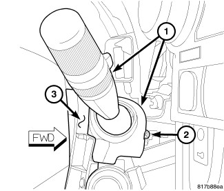
- Remove the screw (2) that secures the right multi-function switch (1) to the mounting bracket integral to the right side of the clockspring (3) on the steering column.
-
Slide the switch away
from the clockspring far enough to disengage the slide tabs on the
switch housing from the channel formations in the mounting bracket.
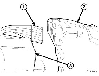
- Disconnect the jumper wire harness connector (1) from the connector receptacle on the inboard end of the right multi-function switch (2).
-
Remove the switch from
the clockspring (3).
INSTALLATION
INSTALLATION
To avoid serious or fatal injury on vehicles equipped with airbags, disable the Supplemental Restraint System (SRS) before attempting any steering wheel, steering column, airbag, seat belt tensioner, impact sensor or instrument panel component diagnosis or service. Disconnect and isolate the battery negative (ground) cable, then wait two minutes for the system capacitor to discharge before performing further diagnosis or service. This is the only sure way to disable the SRS. Failure to take the proper precautions could result in accidental airbag deployment.
WARNING:
|
- Position the right multi-function switch (2) close enough to the mounting bracket (3) integral to the right side of the clockspring to reconnect the jumper wire harness connector (1) to the connector receptacle on the inboard side of the switch housing.
-
Align the slide tabs
on the switch housing with the channel formations integral to the
clockspring mounting bracket, then slide the switch into the bracket
until it is firmly seated.
- Install and tighten the screw (2) that secures the mounting tab on the back of the right multi-function switch (1) to the mounting bracket on the clockspring (3). Tighten the screw to 1 N·m (10 in. lbs.).
- Reinstall the upper and lower shrouds onto the steering column. (Refer to 19 - Steering/Column - Installation) .
-
Reconnect the battery
negative cable.