OUTLET, Power, 115 V
DESCRIPTION
DESCRIPTION
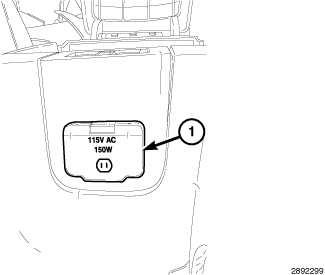 |
The 115 Volt AC outlet (1) is mounted near the lid of the floor console. The vehicle is able to supply 115 Volt AC power through the use of a inverter module. The inverter module is located below the steering column, underneath the steering column opening cover. The inverter converts the 12 Volt DC from the vehicle battery system to a 115 Volt AC output.
The inverter module provides A/C power for user accessories when the 115 Volt AC outlet switch (4) in the instrument panel center stack is in the “ON” position. The outlet switch is part of the instrument panel upper switch pod assembly and is not available for service as an individual part. If the switch is damaged or inoperative the complete upper switch pod assembly must be replaced, (Refer to 08 - Electrical/8J - Instrument Cluster/POD, Switch - Removal)
for the appropriate procedure.
OPERATION
OPERATION
The 115 volt AC power outlet switch receives 12 volts from the Integrated Power Module (IPM) and passes it as an enable signal to the inverter module. The inverter module also receives 12 volts via the IPM and inverts this to a 115 volt AC output. The enable signal received from the power outlet switch enables the inverter to convert the received voltage and pass it to the power outlet to power external devices.
DIAGNOSIS AND TESTING - INVERTER MODULE
DIAGNOSIS AND TESTING - INVERTER MODULE
For complete circuit diagrams, refer to the appropriate wiring information.
Disable the airbag system before attempting any steering wheel, steering column, seat belt tensioner, side airbag or instrument panel component diagnosis or service. Disconnect and isolate the negative battery (ground) cable. Wait two minutes for the airbag system capacitor to discharge before performing further diagnosis or service. This is the only sure way to disable the airbag system. Failure to follow these instructions may result in accidental airbag deployment and possible serious or fatal injury.
WARNING:
115 VOLT POWER OUTLET DIAGNOSIS
|
CONDITION |
POSSIBLE CAUSES |
CORRECTION |
|---|---|---|
|
NO POWER AT THE 115 VOLT POWER OUTLET |
1. Fuse inoperative. |
1. Check Power Distribution Center (PDC) fuse number 23. Replace fuse, if required. |
|
2. Power outlet connector damaged. |
2. Check for loose or corroded power outlet connector. Repair, if required. |
|
|
3. Inverter module connector damaged. |
3. Check for loose or corroded inverter module connector. Repair, if required. |
|
|
4. Wiring damaged. |
4. Check for shorted or open wires. Repair wiring, if required. |
|
|
5. Inverter module ground damaged. |
5. Check for continuity between the inverter module and a known good ground. There should be continuity. Repair ground, if required. |
|
|
6. Power outlet inoperative. |
6. Replace the power outlet. |
|
|
7. Inverter module inoperative. |
7. Replace the inverter module. |
|
|
8. Power outlet switch inoperative. |
6. Replace the accessory switch bank. |
REMOVAL
REMOVAL
 |
- Disconnect and isolate the negative battery cable.
- Open the center console.
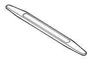
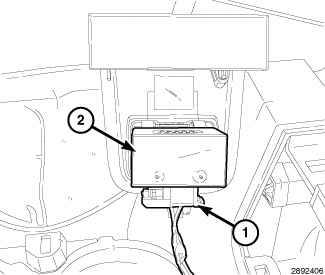
- Using a trim stick C-4755 or equivalent gently pry up on the 115V power outlet assembly to remove.
-
Disconnect the electrical connector (1) from the 115V power outlet.
-
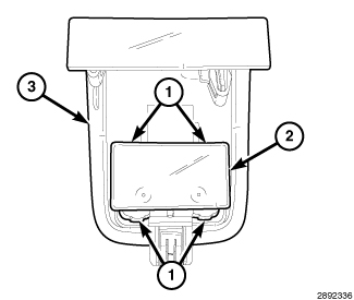
Push in on the four tabs (1) to release the 115V power outlet (2) from the bracket (3).
INSTALLATION
INSTALLATION
|