UNIT, Electrohydraulic Control
DESCRIPTION
DESCRIPTION
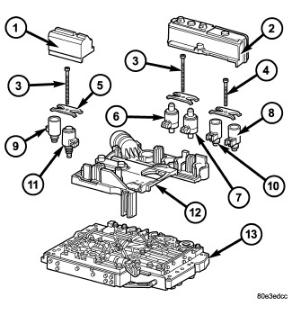
The electrohydraulic control unit comprises the shift plate (13) made from light alloy for the hydraulic control and an electrical control unit (12). The electrical control unit (12) comprises of a supporting body made of plastic, into which the electrical components (1 - 11) are assembled. The supporting body is mounted on the shift plate (13) and screwed to it.
Strip conductors inserted into the supporting body make the connection between the electrical components and a plug connector. The connection to the wiring harness on the vehicle and the transmission control module (TCM) is produced via this 13-pin plug connector with a bayonet lock.
ELECTRICAL CONTROL UNIT
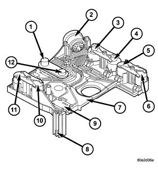
The electric valve control unit (7) consists of a plastic shell which houses the RPM sensors (1,12), regulating solenoid valves (3, 4), solenoid valves (5, 6, 10), the TCC solenoid valve (11), the park/neutral contact (9), and the transmission oil temperature sensor (8). Conductor tracks integrated into the shell connect the electric components to a plug connection (2). This 13-pin plug connection (2) establishes the connection to the vehicle-side cable harness and to the transmission control module (TCM). With the exception of the solenoid valves, all other electric components are fixed to the conductor tracks.
HYDRAULIC CONTROL UNIT
Working Pressure (Line Pressure or Operating Pressure) (p-A)
The working pressure provides the pressure supply to the hydraulic control and the transmission shift elements. It is the highest hydraulic pressure in the entire hydraulic system. The working pressure is regulated at the working pressure regulating valve in relation to the load and gear. All other pressures required for the transmission control are derived from the working pressure.
Lubrication Pressure (p-Sm)
At the working pressure regulating valve surplus oil is diverted to the lubrication pressure regulating valve, from where it is used in regulated amounts to lubricate and cool the mechanical transmission components and the torque converter. Furthermore, the lubrication pressure (p-Sm) is also used to limit the pressure in the torque converter.
Shift Pressure (p-S)
The shift pressure is determined by the shift pressure regulating solenoid valve and the shift pressure regulating valve. The shift pressure:
- Regulates the pressure in the activating shift element during the shift phase.
- Determines together with the modulating pressure the pressure reduction at the deactivating shift element as regulated by the overlap regulating valve.
- Initializes 2nd gear in limp-home mode.
Modulating Pressure (p-Mod)
The modulating pressure influences the size of the working pressure and determines together with the shift pressure the pressure regulated at the overlap regulating valve. The modulating pressure is regulated at the modulating pressure regulating solenoid valve, which is under regulating valve pressure. The modulating pressure is variable and relative to the engine load.
Regulating Valve/Control Valve Pressure (p-RV)
The regulating valve pressure is regulated at the regulating valve pressure regulating valve in relation to the working pressure (p-A) up to a maximum pressure of 8 bar (116 psi). It supplies the modulating pressure regulating solenoid valve, the shift pressure regulating solenoid valve and the shift valve pressure regulating valve.
Shift Valve Pressure (p-SV)
The shift valve pressure (p-SV) is derived from the regulating valve pressure (p-RV), is regulated at the shift valve pressure regulating valve and is then present at the:
- 1-2 and 4-5 shift solenoid valve.
- 3-4 shift solenoid valve.
- 2-3 shift solenoid valve.
- Torque converter lockup solenoid valve.
- 3-4 and 2-3 shift pressure shift valve.
The shift valve pressure (p-SV) controls the command valves via the upshift/downshift solenoid valves.
Overlap Pressure (p-Ü)
The overlap pressure controls the shift component pressure reduction during a shift phase. The pressure in a shift element as it disengages is controlled during the shift phase depending on engine load (modulating pressure) and the pressure in the shift element as it engages. The adjusted pressure is inversely proportional to the transmission capability of the shift element being engaged (controlled overlap).
Working Pressure Regulating Valve (Operating Pressure)
 |
|
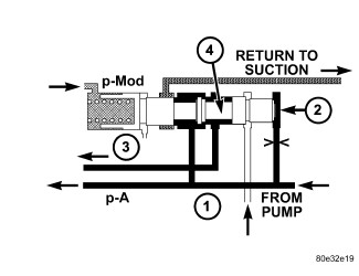
1 - PRESSURE FROM K1/K2 2 - END FACE 3 - TO TORQUE CONVERTER REGULATING VALVE 4 - WORKING PRESSURE REGULATING VALVE |
The working pressure regulating valve (4) is located in the valve housing of the shift plate. It regulates the primary pressure of the hydraulic system.
Torque Converter Lockup Clutch Regulating Valve
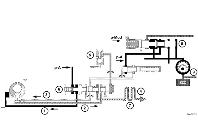
The torque converter lock-up clutch regulating valve (6) is located in the valve housing of the electrohydraulic control module. The valve is responsible for the hydraulic control of the torque converter lockup clutch and distribution of the lubricating oil.
Overlap Regulating Valve
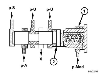 |
|
1 - OVERLAP REGULATING VALVE 2 - ANNULAR SURFACE ON OVERLAP REGULATING VALVE |
Each shift group is assigned one overlap regulating valve (1) . The 1-2 / 4-5 overlap regulating valve is installed in the shift valve housing; the 2-3 and 3-4 overlap regulating valves are installed in the valve housing. The overlap regulating valve regulates the pressure reduction during a shift phase.
Command Valve
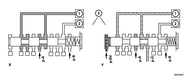 |
|
1 - HOLDING CLUTCH B1 2 - DRIVING CLUTCH K1 3 - 1-2/4-5 COMMAND VALVE |
Each shift group possesses one command valve (3) . The 1-2 / 4-5 and 2-3 command valves are installed in the shift valve housing, the 3-4 command valve is installed in the valve housing. The command valve switches the shift group from the stationary phase to the shift phase and back again.
Holding Pressure Shift Valve
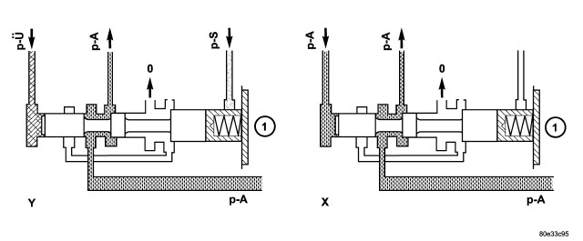 |
|
1 - HOLDING PRESSURE SHIFT VALVE |
Each shift group possesses one holding pressure shift valve (1) . The 1-2 / 4-5 and 2-3 holding pressure shift valves are installed in the shift valve housing; the 3-4 holding pressure shift valve is installed in the valve housing. The holding pressure shift valve allocates the working pressure to one actuator of a shift group.
Shift Pressure Shift Valve
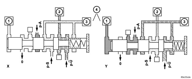 |
|
1 - 1-2/4-5 COMMAND VALVE 2 - DRIVING CLUTCH K1 3 - HOLDING CLUTCH B1 4 - 1-2/4-5 SHIFT PRESSURE SHIFT VALVE |
Each shift group possesses one shift pressure shift valve (4) . The 1-2 / 4-5 and 2-3 shift pressure shift valves are installed in the shift valve housing; the 3-4 shift pressure shift valve is installed in the valve housing. It assigns the shift pressure (p-S) to the activating actuator and the overlap pressure (p-Ü) regulated by the overlap regulating valve to the deactivating actuator.
Lubrication Pressure Regulating Valve
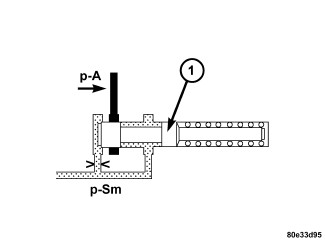 |
The lubrication pressure regulating valve (1) is located in the valve housing of the electrohydraulic control module. The valve controls the fluid to lubricate and cool the mechanical part of the transmission, and limits the pressure in the torque converter.
Shift Pressure Regulating Valve
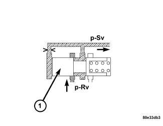 |
The shift pressure regulating valve (1) is located in the valve housing of the shift plate. It regulates the shift pressure (p-S).
Regulating Valve Pressure Regulating Valve
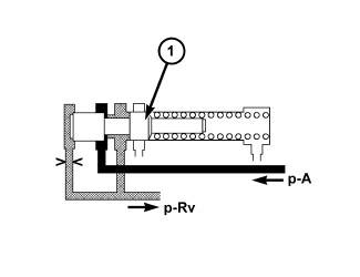 |
The regulating valve pressure regulating valve (1) is located in the valve housing of the electrohydraulic control module. It regulates the regulating valve/control valve pressure (p-RV).
Shift Valve Pressure Regulating Valve
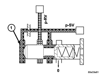 |
The shift valve pressure regulating valve (1) is located in the valve housing of the electrohydraulic control module. It regulates the shift valve pressure (p-SV).
OPERATION
OPERATION
ELECTRICAL CONTROL UNIT
Signals from the transmission control module (TCM) are converted into hydraulic functions in the electric valve control unit (7) . The RPM sensors (1, 12), starter interlock contact (9), and transmission oil temperature sensor (8) of the electric valve control unit (7) supply the TCM with input signals. The solenoid valves are controlled by the TCM and trigger the hydraulic functions.
HYDRAULIC CONTROL UNIT
Working Pressure Regulating Valve (Line Pressure or Operating Pressure)
 |
|
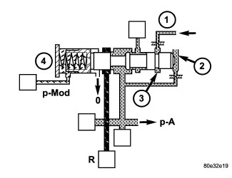
1 - PRESSURE FROM K1/K2 2 - END FACE 3 - ANNULAR SURFACE 4 - WORKING PRESSURE REGULATING VALVE |
The working pressure (p-A) is regulated at the working pressure regulating valve (4) in relation to load (modulating pressure, p-Mod) and gear (K1 or K2 pressure) (1). The spring in the working pressure regulating valve sets a minimum pressure level (basic pressure).
Torque Converter Lockup Clutch Regulating Valve
The torque converter lockup clutch regulating valve (6) regulates the torque converter lock-up clutch working pressure (p-TCC) in relation to the torque converter clutch control pressure (p-S/TCC). According to the size of the working pressure (p-A), the torque converter lockup clutch is either Engaged, Disengaged, or Slipping. When the regulating valve (6) is in the lower position, lubricating oil flows through the torque converter and oil cooler (7) into the transmission (torque converter lockup clutch unpressurized). In its regulating position (slipping, torque converter lockup clutch pressurized), a reduced volume of lubricating oil flows through the annular passage bypassing the torque converter and passing direct through the oil cooler into the transmission. The rest of the lubricating oil is directed via the throttle "a" into the torque converter in order to cool the torque converter lockup clutch.
Overlap Regulating Valve
|
|
|
1 - OVERLAP REGULATING VALVE 2 - ANNULAR SURFACE ON OVERLAP REGULATING VALVE |
During the shift phase the pressure in the deactivating shift actuator is regulated in relation to the engine load (modulating pressure, p-Mod) and the pressure in the activating actuator. The regulated pressure is inversely proportional to the transfer capacity of the activating shift actuator (regulated overlap).
Command Valve
|
|
|
1 - HOLDING CLUTCH B1 2 - DRIVING CLUTCH K1 3 - 1-2/4-5 COMMAND VALVE |
When the end face is unpressurized (stationary phase), the working pressure (p-A) is directed to the actuated shift element. If the end face of the command valve is subjected to the shift valve pressure (p-SV) (shift phase), then the shift pressure (p-S) is switched to the activating element and the overlap pressure (p-Ü) is switched to the deactivating element.
Shift Valve Holding Pressure
|
|
|
1 - HOLDING PRESSURE SHIFT VALVE |
The holding pressure shift valve (1) is actuated by the pressures present at the end face in the actuators and a spring. It assigns the working pressure (p-A) to the actuator with the higher pressure (taking into account the spring force and the effective surface area). The other element of the shift group is then unpressurized. The valve switches over only during the shift phase and only at a certain pressure ratio between the overlap pressure (p-Ü) and the shift pressure (p-S).
Shift Pressure Shift Valve
|
|
|
1 - 1-2/4-5 COMMAND VALVE 2 - DRIVING CLUTCH K1 3 - HOLDING CLUTCH B1 4 - 1-2/4-5 SHIFT PRESSURE SHIFT VALVE |
When the multiple-disc brake B1 (3) is activated, the working pressure (p-A) is applied to the end face of the 1-2 / 4-5 shift pressure shift valve (4) via the command valve (1). Its shift state is maintained during the shift phase by substituting the shift element pressure acting on its end face (and which is variable during the shift phase) with a corresponding constant pressure. When the multi-plate clutch K1 (2) is activated, the end face of the shift valve is unpressurized during the stationary and shift phases, so the shift state is maintained during the shift phase in this case too.
Lubrication Pressure Regulating Valve
|
At the working pressure regulating valve surplus oil is diverted to the lubrication pressure regulating valve (1) , from where the lubrication pressure (p-Sm) is used in regulated amounts to supply the transmission lubrication system including the torque converter.
Shift Pressure Regulating Valve
|
The shift pressure is determined by the shift pressure regulating solenoid valve and the shift pressure regulating valve (1) . In addition, pressure from the clutch K2 is also present at the annular surface of the shift pressure regulating valve. This reduces the shift pressure in 2nd gear.
Regulating Valve Pressure Regulating Valve
|
The regulating valve pressure (p-RV) is set at the regulating valve pressure regulating valve (1) in relation to the working pressure (p-A) as far as the maximum pressure.
Shift Valve Pressure Regulating Valve
|
The non-constant regulating valve pressure (p-RV) is regulated to a constant shift valve pressure (p-SV) at the shift valve pressure regulating valve (1) and is used to supply the 1-2 and 4-5 / 3-4 / 2-3 solenoid valves and the torque converter lockup clutch PWM solenoid valve.
REMOVAL
REMOVAL
 |
- Move selector lever to position "P".
- Raise vehicle.
-
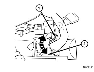
Disconnect 13-pin plug connector (1) . Turn bayonet lock of the adapter plug (2) anti-clockwise.
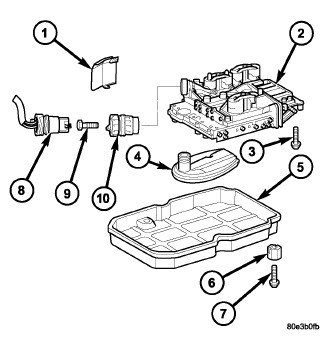
- Loosen the adapter plug bolt (9) and remove from the adapter plug (10) from the transmission housing.
- Detach oil pan (5).
- Remove oil filter (4).
-
Unscrew Torx® socket bolts (3) and remove electrohydraulic control module (2).
DISASSEMBLY
DISASSEMBLY
- Remove electrohydraulic unit from the vehicle. (Refer to 21 - Transmission and Transfer Case/Automatic - NAG1/UNIT, Electrohydraulic Control - Removal)
- Remove solenoid caps (1, 2) if equipped.
-
Unscrew Torx® socket bolts (3, 4).
NOTE: Pay attention to the different lengths of the Torx® socket bolts.
- Remove leaf springs (5).
-
Withdraw solenoid valves (6 - 11) from shift plate (13).
NOTE: Check O-rings on solenoid valves for damage and replace if necessary.
- Bend away retaining lug on stiffening rib on transmission oil temperature sensor.
-
Remove electrohydraulic control module (12) from the shift plate (13).
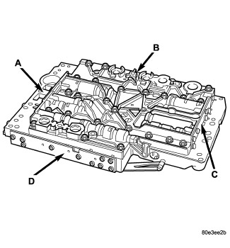
Shift Valve Group Locations
-
Note the locations of the major shift valve group components for assembly reference.
- A - Operating and Lubricating Pressure Regulating valves and 2-3 Overlap valve
- B - 1-2/4-5 Shift Group and Shift, Shift Valve, and Regulating Valve Pressure Regulating Valves
- C - 3-4 Shift Group
-
D - 2-3 Shift Group, TCC Lock-up, and B2 Regulating Valves
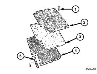
1 - BOLTS - 29
2 - VALVE HOUSING
3 - SEALING PLATE
4 - VALVE BODY
5 - LEAF SPRING
NOTE: Pay great attention to cleanliness for all work on the shift plate. Fluffy cloths must not be used. Leather cloths are particularly good. After dismantling, all parts must be washed and blown out with compressed-air, noting that parts may be blown away.
- Unbolt leaf spring (5).
- Unscrew Torx® bolts (1).
- Remove valve housing (2) from valve body (4).
-
Remove sealing plate (3).
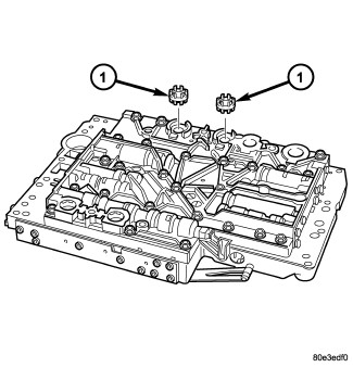
Solenoid Valve Strainer Locations
-
Remove the strainers (1) for the modulating pressure and shift pressure control solenoid valves from the valve housing.
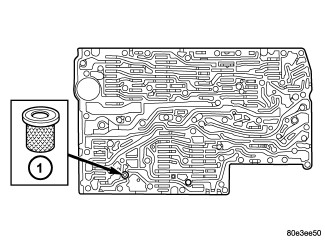
1 - CONVERTER LOCK-UP SOLENOID STRAINER
-
Remove the strainer (1) in the inlet to torque converter lock-up control solenoid valve.
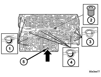
1 - STEEL CHECK BALLS
2 - CENTRAL STRAINER
3 - STEEL CHECK BALLS
4 - PLASTIC CHECK BALLS
5 - PLAIN DOWEL PIN
NOTE: A total of 12 valve balls are located in the valve body, four made from plastic (4) and eight from steel (1, 3).
-
Note the location of all check balls (1, 3, 4) and the central strainer (2) for re-installation. Remove all check balls (1, 3, 4) and the central strainer (2).
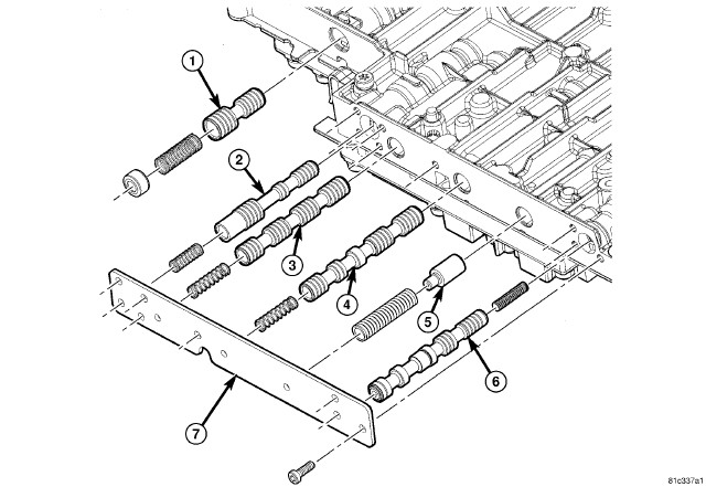
- Remove the screws holding the side cover (7) to the valve body and valve housing.
- Remove the B-2 Shift Valve assembly (1), 2-3 Holding Pressure Valve assembly (2), 2-3 Command Valve assembly (3), 2-3 Shift Pressure assembly (4), TCC Damper Valve (5) if equipped and the TCC Lock-Up Regulator Valve assembly (6) from the valve body.
-
Check all valves for ease of movement and shavings.
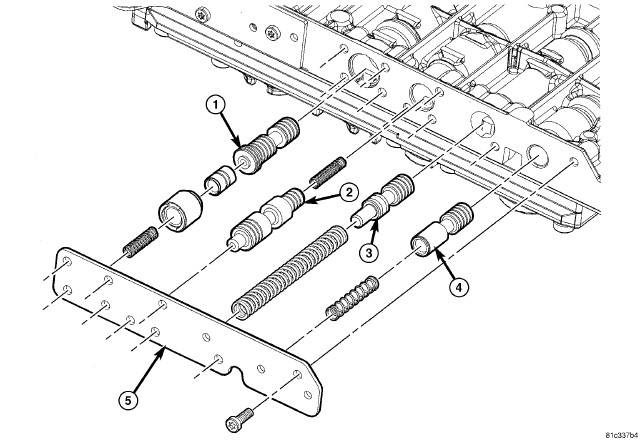
- Remove the screws holding the side cover (5) to the valve body and valve housing.
- Remove the 1-2 / 4-5 Overlap Regulating Valve, Sleeve, and Piston assembly (1), Shift Pressure Regulating Valve assembly (2), Control Valve Pressure Regulator assembly (3), and the Shift Solenoid Pressure Regulating Valve (4) from the valve body.
-
Check all valves for ease of movement and shavings.
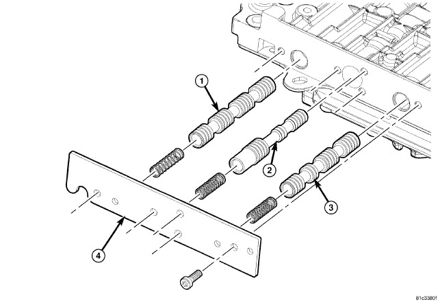
- Remove the screws holding the side cover (4) to the valve body and valve housing.
- Remove the 1-2 / 4-5 Command valve assembly (1), 1-2 / 4-5 Holding Pressure Shift Valve (2) and the 1-2 / 4-5 Shift Pressure Shift Valve assembly (3) from the valve body.
-
Check all valves for ease of movement and shavings.
NOTE: The sleeves and pistons of the overlap regulating valves must not be mixed up.
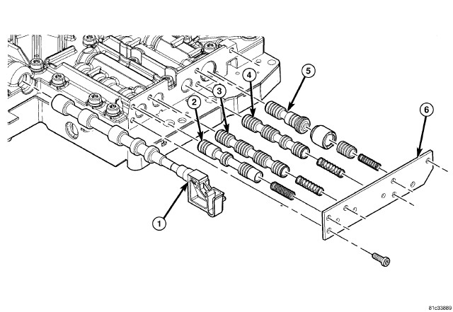
- Remove the screws holding the side cover (6) to the valve body and valve housing.
- Remove the sector valve (1).
- Remove 3-4 Holding Pressure Shift Valve assembly (2), 3-4 Command Valve assembly (3), 3-4 Shift Pressure Shift Valve assembly (4) and the 3-4 Overlap Regulating Valve Sleeve and Piston assembly (5) from the valve body.
-
Check all valves for ease of movement and shavings.
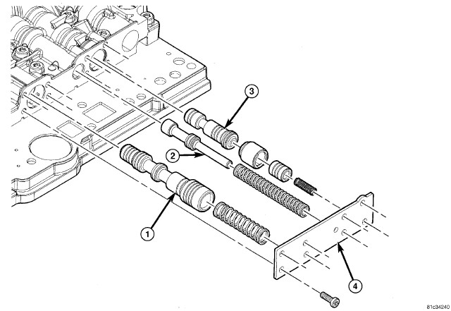
- Remove the screws holding the side cover (4) to the valve body and valve housing.
- Remove the Line Pressure Regulating Valve assembly (1), Lubricating Pressure Regulating Valve assembly (2) and the 2-3 Overlap Regulating Valve, Sleeve and Piston assembly (3) from the valve body.
-
Check all valves for ease of movement and shavings.
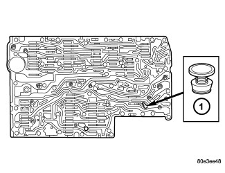
1 - PRESSURE FEED VALVE
-
Remove the pressure supply valve (1) from the valve body.
CLEANING
CLEANING
| NOTE: |
Fine and extremely fine metallic particles have been known affect valve operation in this transmission. While these particles may be to small to see with the naked eye, they can cause flares, or momentary going into neutral, on shifts. |
Clean and flush the valve housings, valves, plugs, springs, and separator plates thoroughly with a standard parts cleaning solution only. Do not use gasoline, kerosene, or any type of caustic solution.
Do not immerse any of the electrical components in cleaning solution. Clean the electrical components by wiping them off with dry shop towels only.
Dry all except the electrical parts with compressed air. Make sure all passages are clean and free from obstructions. Do not use rags or shop towels to dry or wipe off valve body components. Lint from these materials can stick to valve body parts, interfere with valve operation, and clog filters and fluid passages.
INSPECTION
INSPECTION
Inspect all of the valve body mating surfaces for scratches, nicks, burrs, or distortion. Use a straightedge to check surface flatness. Minor scratches may be removed with crocus cloth using only very light pressure.
Minor distortion of a valve body mating surface may be corrected by smoothing the surface with a sheet of crocus cloth. Position the crocus cloth on a surface plate, sheet of plate glass or equally flat surface. If distortion is severe or any surfaces are heavily scored, the valve body will have to be replaced. If crocus cloth is used be certain to flush valve body thoroughly. .
Inspect the valves and plugs for scratches, burrs, nicks, or scores. Minor surface scratches on steel valves and plugs can be removed with crocus cloth but do not round off the edges of the valve or plug lands. Maintaining sharpness of these edges is vitally important. The edges prevent foreign matter from lodging between the valves and plugs and the bore.
Inspect all the valve and plug bores in the valve body. Use a penlight to view the bore interiors. Replace the valve body if any bores are distorted or scored. Inspect all of the valve body springs. The springs must be free of distortion, warpage or broken coils.
Trial fit each valve and plug in its bore to check freedom of operation. When clean and dry, the valves and plugs should drop freely into the bores.
Valve body bores do not change dimensionally with use. If the valve body functioned correctly when new, it will continue to operate properly after cleaning and inspection. It should not be necessary to replace a valve body assembly unless it is damaged in handling.
ASSEMBLY
ASSEMBLY
Make certain all valves and springs
are assembled correctly. Failure to follow this caution may result
in transmission failure.
CAUTION:
| NAG1 VALVE BODY SPRING DIMENSION | ||
|---|---|---|
|
VALVE |
SPRING FREE LENGTH |
TOTAL COILS |
|
2-3 Holding |
18.8 -19.6 mm (0.74 - 0.77 in.) |
12 |
|
T/C Clutch Damper |
37.5 - 38.5 mm (1.48 - 1.51 in.) |
19.5 |
|
1-2 / 4-5 Overlap |
20.95 - 21.65 mm (0.82 - 0.85 In.) |
14.5 |
|
Shift Pressure Regulator |
22.4 - 23.6 mm (0.88 - 0.93 in.) |
14.5 |
|
Control Valve Pressure Regulator |
79.2 - 82.4 mm (3.12 - 3.24 in.) |
29 |
|
Shift Solenoid Pressure Regulating Valve |
32.6 - 34.4 mm (1.28 - 1.35 in.) |
15.5 |
|
T/C Clutch (LU) Regulator |
22.8 - 23.6 mm (0.90 - 0.93 in.) |
18.5 |
|
B2 Shift Valve |
25.8 - 27.0 mm (1.01 - 1.06 in.) |
16.5 |
|
3/4 Over Lap |
21.0 - 20.4 mm (0.83 - 0.80 in.) |
13 |
|
3-4 Holding, 1-2 / 4-5 Holding, 1-2 / 4-5 Shift Pressure |
21.1 - 22.5 mm (0.83 - 0.88 in.) |
14 |
|
3-4 Command, 3-4 Shift Pressure, 1-2 / 4-5 Command, 2-3 Shift Pressure, 2-3 Command |
23.9 - 25.3 mm (0.94 -1.00 in.) |
11.5 |
|
Lubricating Pressure Regulating Valve |
64.8 - 68.2 mm (2.55 - 2.68 in.) |
24 |
|
2-3 Overlap |
16.9 - 18.7 mm (0.66 - 0.74 in.) |
13 |
|
Line Pressure Regulator |
43.8 - 46.2 mm (1.72 - 1.82 in.) |
13.5 |
| NOTE: |
Pay great attention to cleanliness for all work on the shift plate. Fluffy cloths must not be used. Leather cloths are particularly good. After dismantling, all parts must be washed and blown out with compressed-air, noting that parts may be blown away. |
|
|
|
1 - PRESSURE FEED VALVE |
-
Install the pressure
supply valve (1) into the valve body.
NAG1 VALVE BODY SPRING DIMENSION VALVE
SPRING FREE LENGTH
TOTAL COILS
2-3 Holding (2)
18.8 -19.6 mm (0.74 - 0.77 in.)
12
T/C Clutch Damper (5)
37.5 - 38.5 mm (1.48 - 1.51 in.)
19.5
T/C Clutch (LU) Regulator (6)
22.8 - 23.6 mm (0.90 - 0.93 in.)
18.5
B2 Shift Valve (1)
25.8 - 27.0 mm (1.01 - 1.06 in.)
16.5
2-3 Shift Pressure (4), 2-3 Command (3)
23.9 - 25.3 mm (0.94 -1.00 in.)
11.5
- Lubricate and install the B-2 Shift Valve assembly (1), 2-3 Holding Pressure Valve assembly (2), 2-3 Command Valve assembly (3), 2-3 Shift Pressure Shift Valve assembly (4), TCC Damper Valve (5) if equipped and the T/CC Lock-Up Regulator Valve assembly (6) into the valve body.
-
Install the side cover
and the screws holding the side cover (7) to the valve body and valve
housing. Tighten the screws to 4 N·m (35 in.lbs.).
NAG1 VALVE BODY SPRING DIMENSION VALVE
SPRING FREE LENGTH
TOTAL COILS
1-2 / 4-5 Overlap (1)
20.95 - 21.65 mm (0.82 - 0.85 In.)
14.5
Shift Pressure Regulator (2)
22.4 - 23.6 mm (0.88 - 0.93 in.)
14.5
Control Valve Pressure Regulator (3)
79.2 - 82.4 mm (3.12 - 3.24 in.)
29
Shift Solenoid Pressure Regulating Valve (4)
32.6 - 34.4 mm (1.28 - 1.35 in.)
15.5
- Lubricate and install the 1-2 / 4-5 Overlap Regulating Valve, Sleeve, and Piston assembly (1), Shift Pressure Regulating Valve assembly (2), Control Valve Pressure Regulator Valve assembly (3) and Shift Solenoid Pressure Regulating Valve assembly (4) into the valve body.
-
Install the side cover
and the screws holding the side cover (5) to the valve body and valve
housing. Tighten the screws to 4 N·m (35 in.lbs.).
NAG1 VALVE BODY SPRING DIMENSION VALVE
SPRING FREE LENGTH
TOTAL COILS
1-2 / 4-5 Holding (2), 1-2 / 4-5 Shift Pressure (3)
21.1 - 22.5 mm (0.83 - 0.88 in.)
14
1-2 / 4-5 Command (1)
23.9 - 25.3 mm (0.94 -1.00 in.)
11.5
- Lubricate and install the 1-2 / 4-5 Command valve assembly (1), 1-2 / 4-5 Holding Pressure Shift Valve (2) and the 1-2 / 4-5 Shift Pressure assembly (3) into the valve body.
-
Install the side cover
and the screws holding the side cover (4) to the valve body and valve
housing. Tighten the screws to 4 N·m (35 in.lbs.).
NAG1 VALVE BODY SPRING DIMENSION VALVE
SPRING FREE LENGTH
TOTAL COILS
3/4 Over Lap (5)
20.4 - 21.0 mm (0.80 - 0.83 in.)
13
3-4 Holding (2)
21.1 - 22.5 mm (0.83 - 0.88 in.)
14
3-4 Command (3), 3-4 Shift Pressure (4)
23.9 - 25.3 mm (0.94 -1.00 in.)
11.5
- Lubricate and install the sector valve (1).
- Lubricate and install 3-4 Holding Pressure Shift Valve assembly (2), 3-4 Command Valve assembly (3), 3-4 Shift Pressure assembly (4) and the 3-4 Overlap Regulating Valve Sleeve and Piston assembly (5) into the valve body.
-
Install the side cover
and the screws holding the side cover (6) to the valve body and valve
housing. Tighten the screws to 4 N·m (35 in.lbs.).
NAG1 VALVE BODY SPRING DIMENSION VALVE
SPRING FREE LENGTH
TOTAL COILS
Lubricating Pressure Regulating Valve (2)
64.8 - 68.2 mm (2.55 - 2.68 in.)
24
2-3 Overlap (3)
16.9 - 18.7 mm (0.66 - 0.74 in.)
13
Line Pressure Regulator (1)
43.8 - 46.2 mm (1.72 - 1.82 in.)
13.5
- Lubricate and install the Operating Pressure Regulating Valve assembly (1), Lubricating Pressure Regulating Valve assembly (2) and the 2-3 Overlap Regulating Valve, Sleeve and Piston assembly (3) into the valve body.
-
Install the side cover
and the screws holding the side cover (6) to the valve body and valve
housing. Tighten the screws to 4 N·m (35 in.lbs.).
1 - STEEL CHECK BALLS
2 - CENTRAL STRAINER
3 - STEEL CHECK BALLS
4 - PLASTIC CHECK BALLS
5 - PLAIN DOWEL PIN
NOTE: A total of 12 valve balls are located in the valve body, four made from plastic (4) and eight from steel (1, 3).
-
Install all check balls
(1, 3, 4) and the central strainer
(2).
1 - CONVERTER LOCK-UP SOLENOID STRAINER
-
Install the strainer
(1) in the inlet to torque
converter lock-up control solenoid valve.
1 - BOLTS - 29
2 - VALVE HOUSING
3 - SEALING PLATE
4 - VALVE BODY
5 - LEAF SPRING
- Position the sealing plate (3) onto the valve body (4) .
- Install the valve housing (2) onto the valve body (4) and sealing plate (3).
- Install the shift plate Torx® bolts (1) . Tighten the bolts to 8 N·m (71 in.lbs.).
-
Install leaf spring
(5) .
Solenoid Valve Strainer Locations
-
Install the strainers
(1) for the modulating pressure and shift pressure control solenoid
valves into the valve housing.
- Install the electrohydraulic control module (12) onto the shift plate (13) .
- Bend the retaining lug on stiffening rib on transmission oil temperature sensor to retain the electrohydraulic control module.
-
Install the solenoid
valves (6 - 11) into shift plate (13).
NOTE: Check O-rings on solenoid valves for damage and replace if necessary.
- Install the leaf springs (5).
-
Install the Torx® socket
bolts (3, 4) . Tighten the bolts
to 8 N·m (71 in.lbs.).
NOTE: Pay attention to the different lengths of the Torx® socket bolts.
- Install the solenoid caps (1, 2) if equipped.
-
Install the electrohydraulic
unit into the vehicle.
INSTALLATION
INSTALLATION
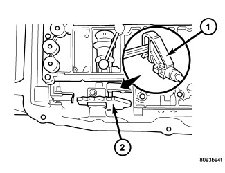 |
- Position the electrohydraulic unit in the transmission housing.
-
Insert selector valve (1) in driver of detent plate (2). When installing the electrohydraulic control module in the transmission housing, the plastic part of the selector valve (1) must engage in the driver of the detent plate (2).
- Install the Torx® socket bolts (3) and torque to 8 N·m (71 in.lbs.).
- Install a new oil filter (4) .
- Install oil pan (5) and torque the oil pan bolts to 8 N·m (71 in.lbs.).
-
Install the adapter plug (10) into the transmission housing and tighten the bolt (9) to 2.5 N·m (22 in.lbs.).
- Check O-ring on plug connector (1) , and replace if necessary.
- Install the plug connector (1) into the adapter plug (2). Turn bayonet lock of adapter plug (2) clockwise to connect plug connector (1).
-
Fill the transmission with the correct oil (Refer to 04 - Vehicle Quick Reference/Capacities and Recommended Fluids - Description)
using the standard procedure (Refer to 21 - Transmission and Transfer Case/Automatic - NAG1/FLUID and FILTER - Standard Procedure)
.