COVER, Engine, Front
DESCRIPTION
DESCRIPTION
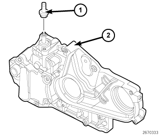 |
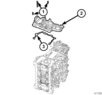
The front engine cover (2) incorporates the engine oil pump and vacuum pump. Neither of these components are serviceable, but only as a whole assembly.
REMOVAL
REMOVAL
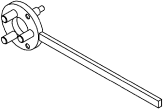
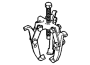
Special Tools: Click to display a list of tools used in this procedure
 |
- Disconnect the negative battery cable.
- Drain the cooling system (Refer to 07 - Cooling - Standard Procedure) .
-
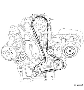
Remove the timing belt (Refer to 09 - Engine/Valve Timing/BELT, Timing - Removal)
.
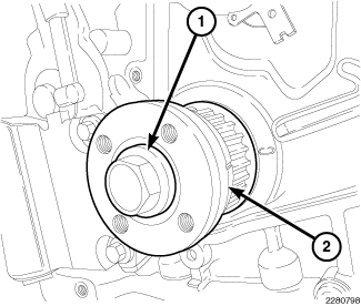
NOTE: The crankshaft sprocket bolt is a left handed thread.
-
Remove bolt (1), and the crankshaft sprocket (2).
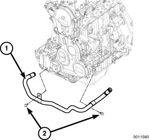
- Disconnect the coolant tube hose at oil cooler and by fuel injection pump.
-
Remove bolts (2), and the coolant tube (1).
-
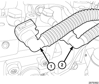
Disconnect the low pressure supply (1) and return (2) lines at injection pump.
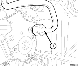
- Remove the fuel quantity solenoid (Refer to 14 - Fuel System/Fuel Delivery/SOLENOID, Fuel Quantity - Removal) .
-
Remove the high-pressure fuel tube (1) at rear of pump and fuel rail.
-
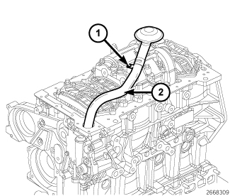
Remove the oil pump pickup tube (Refer to 09 - Engine/Lubrication/PICK-UP, Oil Pump - Removal)
.
- Disconnect the vacuum hose at vacuum pump.
-
Remove the eight bolts (1), and the front cover assembly (2).
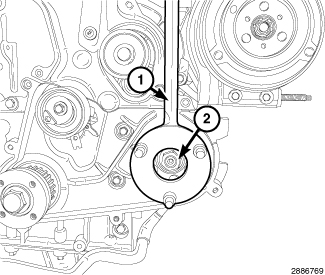
- If necessary, using Locking Tool VM.1055 (1) remove the injection pump sprocket nut (2).
- If necessary, attach a Puller 1023 and remove sprocket from pump.
-
If necessary, remove nuts and the injection fuel pump.
-
If necessary, remove the vacuum pump check valve.
INSTALLATION
INSTALLATION
Special Tools: Click to display a list of tools used in this procedure
|
- Clean all gasket mating surfaces.
- If necessary, install the front crankshaft oil seal (Refer to 09 - Engine/Engine Block/SEAL, Crankshaft Oil - Installation) .
-
If necessary, transfer
the vacuum pump check valve (1) and securely tighten.
- If necessary, install the high pressure fuel pump. Tighten nuts to 24 N·m (18 ft. lbs.).
-
If necessary, using
Locking Tool VM.1055 , install the high pressure fuel pump sprocket. Tighten nut
(2) to 88 N·m (65 ft. lbs.).
- Install the front cover gasket (3).
-
Install the front cover
assembly (2) and tighten the eight bolts (1) finger tight.
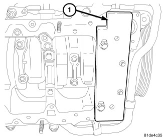
-
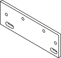
Install the
Tool, Front And Rear Seal VM.9990 (1) to align the front cover.
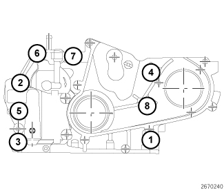
- Using the tightening sequence shown, tighten bolts to 33 N·m (24 ft. lbs.).
-
Remove the Front
and Rear Seal Tool 9990.
-
Install the oil pump
pickup tube (Refer to 09 - Engine/Lubrication/PICK-UP,
Oil Pump - Installation)
.
- Install the new high-pressure fuel tube (1) at rear of pump and fuel rail.
-
Install the fuel quantity
solenoid (Refer to 14 - Fuel
System/Fuel Delivery/SOLENOID, Fuel Quantity - Installation)
.
-
Connect the low pressure
supply (1) and return (2) lines at injection pump.
- Install the coolant tube (1). Tighten bolts (2) to 15 N·m (133 in. lbs.).
-
Connect the coolant
tube hose at oil cooler and by fuel injection pump.
NOTE: The crankshaft sprocket bolt is a left handed thread.
-
Install the crankshaft
sprocket (2). Tighten bolt to 100 N·m (74 ft. lbs.) plus an additional
120 degrees.
- Install the timing belt (Refer to 09 - Engine/Valve Timing/BELT, Timing - Installation) .
- Fill the cooling system (Refer to 07 - Cooling - Standard Procedure) .
-
Connect the negative
battery cable.