RAIL, Fuel
REMOVAL
REMOVAL
Cleanliness cannot be overemphasized
when handling or replacing diesel fuel system components. This especially
includes the fuel injectors, high-pressure fuel lines and fuel injection
pump. Very tight tolerances are used with these components. Dirt contamination
can cause rapid part wear and possibly plug fuel injector nozzle tips.
This in turn could lead to possible engine misfire. Always clean any
fuel system component thoroughly before disassembly and then air dry.
Cap or cover any open component after disassembly. Before assembly,
examine each component for dirt, grease or other contaminants and
clean if necessary. When installing new components, lubricate them
for assembly with clean engine oil or clean diesel fuel only.
CAUTION:
Any time a high pressure fuel
line has been loosened or disconnected, that high pressure fuel line
must be replaced. Failure to follow these instructions may lead to
a high pressure fuel leak.
CAUTION:
 |
- Disconnect the negative battery cable.
- Center and lock the steering wheel.
- Remove the four nuts and the engine cover.
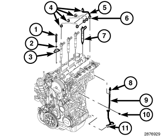
- Disconnect the fuel pressure sensor (1) harness connector.
-
Disconnect the fuel pressure solenoid (3) harness connector.
CAUTION: When loosening or tightening high-pressure line fittings, use a back-up wrench on each fitting. Do not allow any fitting to rotate. Damage to both fuel line and fitting will result.
- Disconnect fuel tube fittings (4) and (6) and remove four fuel tubes (5) and install a protective caps on the fuel injector and fuel rail. Note and mark position of each fuel tube while removing.
- Disconnect the Charge Air Cooler (CAC) outlet hose from the EGR air flow control valve.
- Disconnect the EGR air flow control valve harness connector.
- Remove the air cleaner body (Refer to 09 - Engine/Air Intake System/BODY, Air Cleaner - Removal) .
- Partially remove the serpentine belt.
- Remove the generator (Refer to 08 - Electrical/8F - Engine Systems/Charging/GENERATOR - Removal) .
- Remove the lower intermediate shaft-to-upper intermediate shaft pinch bolt and disconnect the intermediate shaft.
-
Remove the A/C compressor and position aside.
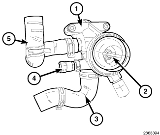
- Remove the thermostat housing (Refer to 07 - Cooling/Engine/THERMOSTAT - Removal) .
- Remove the water inlet elbow (Refer to 07 - Cooling/Engine/TUBE, Water Inlet - Removal) .
-
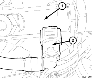
Disconnect the fuel quantity solenoid harness connector.
-
Disconnect the fuel return (2) line from fuel rail (1).
- Remove the fuel line clamp bolt (10).
-
Disconnect rail-to-injection pump high-pressure fuel tube fittings (8) and (11). Remove and discard fuel tube (9).
-
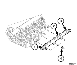
Remove three nuts (4) and the fuel rail.
INSTALLATION
INSTALLATION
| NOTE: |
New High Pressure Fuel Line must be used any time the High Pressure Fuel Lines have been removed. |
Cleanliness cannot be overemphasized
when handling or replacing diesel fuel system components. This especially
includes the fuel injectors, high-pressure fuel lines and fuel injection
pump. Very tight tolerances are used with these parts. Dirt contamination
could cause rapid part wear and possible plugging of fuel injector
nozzle tip holes. This in turn could lead to possible engine misfire.
Always wash/clean any fuel system component thoroughly before disassembly
and then air dry. Cap or cover any open part after disassembly. Before
assembly, examine each part for dirt, grease or other contaminants
and clean if necessary. When installing new parts, lubricate them
with clean engine oil or clean diesel fuel only.
CAUTION:
|
- Position fuel rail (2) to cylinder head.
-
Install three fuel rail mounting nuts (4). Tighten nuts (alternately) to 24 N·m (18 ft. lbs.).
CAUTION: WHEN LOOSENING OR TIGHTENING HIGH-PRESSURE LINE FITTINGS ATTACHED TO A SEPARATE FITTING, USE A BACK-UP WRENCH ON FITTING. DO NOT ALLOW FITTING TO ROTATE. DAMAGE TO BOTH FUEL LINE AND FITTING WILL RESULT.
NOTE: When ever a fuel tube connection is loosened, new fuel tubes MUST be used.
- Install the new fuel tube (9) and connect rail-to-injection pump high-pressure fuel line fittings (8) and (11).
- Tighten the high pressure fuel feed tube at the high pressure pump (11) to 28 N·m (20 ft. lbs.).
- Tighten the high pressure fuel feed tube at the fuel rail (8) to 5 N·m (44 in. lbs) plus an additional 75 degrees.
-
Install fuel line clamp bolt (10). Tighten to 15 N·m (133 in. lbs.).
-
Connect the fuel return (2) line from fuel rail (1).
- Connect the fuel quantity solenoid harness connector.
- Install the water inlet elbow (Refer to 07 - Cooling/Engine/TUBE, Water Inlet - Installation) .
-
Install the thermostat housing (Refer to 07 - Cooling/Engine/THERMOSTAT - Installation)
.
- Install the A/C Compressor. Tighten the bolts to 28 N·m (21 ft. lbs.).
- Connect the upper intermediate shaft-to-lower intermediate shaft. Tighten pinch bolt to 49 N·m (36 ft. lbs.).
- Install the generator (Refer to 08 - Electrical/8F - Engine Systems/Charging/GENERATOR - Installation)
- Install the serpentine belt.
- Install the air cleaner body (Refer to 09 - Engine/Air Intake System/BODY, Air Cleaner - Installation) .
- Connect the EGR air flow control valve harness connector.
- Connect the Charge Air Cooler (CAC) outlet hose from the EGR air flow control valve.
- Remove the protective caps from the fuel injectors and install new high pressure fuel tubes (5). Only hand tighten the high pressure fuel line (4) and (6).
- Tighten the high pressure fuel tube (4) on the fuel injector to 28 N·m (20 ft. lbs.).
-
Tighten the high pressure fuel tube (6) on the fuel rail to 5 N·m (44 in. lbs) plus an additional 75 degrees.
- Connect the fuel pressure solenoid (3) harness connector.
- Connect the fuel pressure sensor (1) harness connector.
- Install the engine cover and securely tighten the four nuts.
- Remove the steering wheel lock.
-
Connect the negative battery cable.