PANEL, Instrument
REMOVAL
REMOVAL
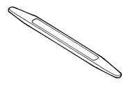
Special Tools: Click to display a list of tools used in this procedure
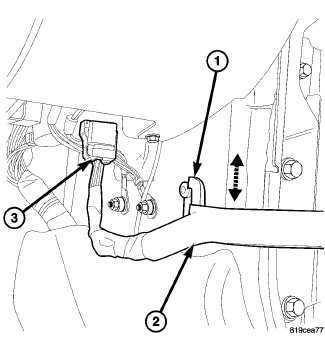 |
- Disconnect the electrical connector (3) at the A-pillar cowl area and separate the check strap (2) from the footmans loop (1).
-
Open the doors past
90°, to aid in the removal of the I/P assembly.
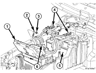
- Disconnect and isolate the negative battery cable.
-
Remove the center console. (Refer to 23 - Body/Interior/CONSOLE,
Center - Removal)
.
-
Disconnect the center
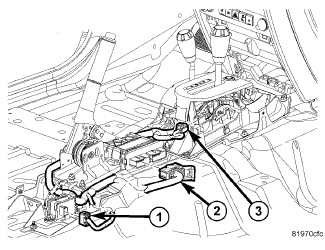
I/P wire harness electrical connectors (1, 2 and 3).
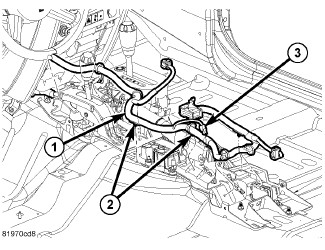
- Release the push pin hangers (2) and position aside the harness (1).
- Remove the steering column opening cover. (Refer to 23 - Body/Instrument Panel/COVER, Steering Column Opening - Removal)
- Remove the amplifier.
-
Remove the steering
column as necessary. (Refer
to 19 - Steering/Column - Removal)
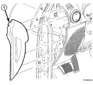
- Using a trim stick C-4755 or equivalent, remove the end caps (1).
- On automatic transmission vehicles, remove the shifter.
- Remove the transfer case shifter. (Refer to 21 - Transmission and Transfer Case/Transfer Case/LEVER, Transfer Case - Removal) .
-
Remove the radio.
-
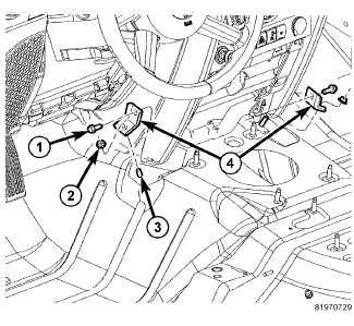
Remove the nuts (2)
and bolts (1) and the center support brackets (4).
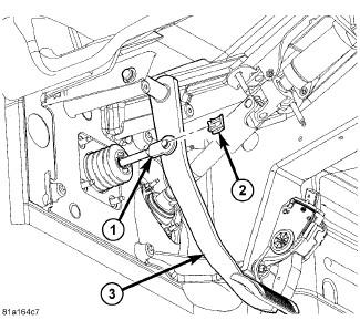
- Remove the clutch pedal clip and separate the clutch pedal rod, if equipped.
-
Remove the brake pedal
clip (2) and separate the brake pedal rod (1).
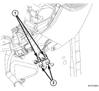
-
Remove the nuts and
separate the grounds (2).
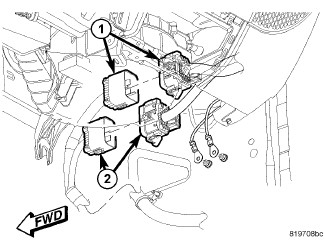
- Disconnect the driver side electrical connectors.
-
Disconnect the passenger
side electrical connectors (1 and 2).
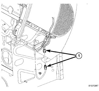
-
Disconnect the antenna
connector (1).
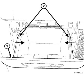
-
Remove the glove box
(1).
- Disconnect the positive battery cable.
- Remove the right side ground.
- Position aside the power steering reservoir.
- Remove the battery tray.
- Drain the refrigerant. (Refer to 24 - Heating and Air Conditioning/Plumbing - Standard Procedure) .
-
Drain the coolant. (Refer to 07 - Cooling - Standard
Procedure)
.
- Remove the upper intake manifold. (Refer to 09 - Engine/Manifolds/MANIFOLD, Intake - Removal)
-
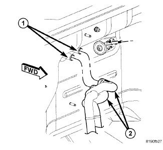
Using cable-type spring
clamp pliers or equivalent, release the hose clamps securing the heater
hoses (2) to the heater core tubes (1). Disconnect the hoses from
the tubes. Install plugs in, or tape over the opened heater core tubes
to prevent coolant spillage during the HVAC housing assembly removal.

- Remove the nut (2) that securing the A/C liquid line (3) and A/C suction line (5) to the A/C expansion valve (1).
- Disconnect the A/C liquid and suction lines from the A/C expansion valve. Remove and discard the O-ring seals.
-
Install plugs in or
tape over the opened the refrigerant line fittings and the expansion
valve ports.
- Position aside the harness at the brake booster.
-
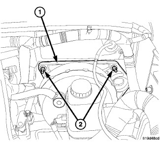
Remove the brake booster
bracket nuts (2).
-
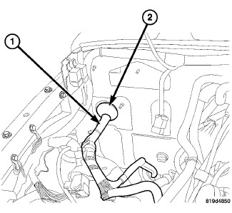
Release the wire harness
grommet (2) and separate any remaining support clips for the wires
harness (1).

-
Remove the trim caps
(2) and the fenceline nuts (3).
-
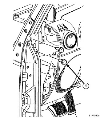
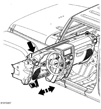
Remove the side support
bolts (1) and position the I/P assembly back.
-
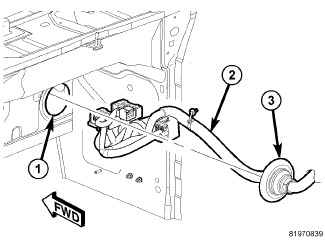
Pull the main wire
harness (2) from the hole in the cowl (1).
-
Remove the I/P from
the vehicle.
INSTALLATION
INSTALLATION
|
-
Position the I/P assembly
into the vehicle and support the back.
-
Position the wire harness
(2) through the cowl panel (1) and seat the grommet (3) fully.
- Loosely install the nuts (3) onto the fenceline studs (1).
- Position the I/P assembly (4) back and carefully push the heater core, A/C lines, and the brake booster support studs, through the cowl.
-
Position the I/P over
the fenceline studs (1).
-
Loosely install the
side support bolts (1).
-
Install the center
support brackets (4) over the studs (3) and install the bolts (1)
and nuts (2).
-
Tighten the side support
bolts to 11 N·m (8 ft. lbs.).
-
Tighten the fenceline
nuts to 12 N·m (9 ft. lbs.).
-
Tighten the bolts (1)
and nuts (2) to 8 N·m (71 in. lbs.).
-
Position the main wire
harness (1) back into place and seat all the support clips fully.
- Install the brake booster bracket nuts (2) and tighten to 18 N·m (13.3 ft. lbs.).
-
Position the wire harness
back and secure the support clips fully.
- Remove the tape or plugs from the opened refrigerant line fittings and the expansion valve ports.
- Lubricate the new O-ring seals with clean refrigerant oil and install them onto the refrigerant line fittings. Use only the specified O-rings, as they are made of special materials compatible to the R-134a system. Use only refrigerant oil of the type recommended for the A/C compressor in the vehicle.
- Connect the A/C liquid line (3) and A/C suction line (5), onto the A/C expansion valve (1).
-
Install the nut (2)
that securing the A/C liquid and suction lines to the A/C expansion
valve. Tighten the nut to 23 N·m (17 ft. lbs.).
- Remove the previously installed plugs or caps and connect the heater hoses (2) to the heater core tubes (1).
- Using the cable-type spring clamp pliers or equivalent, correctly position the two hose clamps securing the heater hoses to the heater core tubes and engage the clamps to the tubes.
- Fill the coolant. (Refer to 07 - Cooling - Standard Procedure) .
-
Charge the A/C system. (Refer to 24 - Heating and Air Conditioning/Plumbing
- Standard Procedure)
.
- Install the battery tray.
- Position the power steering reservoir back into place.
- Install the right side grounds (2) and install the nuts (3).
-
Connect the positive
battery cable (4).
-
Install the glove box
(1). (Refer to 23 - Body/Instrument
Panel/GLOVE BOX, Instrument Panel - Installation)
.
-
Connect the antenna
connector (1).
-
Connect the electrical
connectors (1 and 2).
- Connect the grounds (2) and install the nuts.
-
Install the nut to
the lower HVAC support bracket under the glove box.
- Connect the brake pedal rod (1) and install the clip (2).
- If equipped, connect the clutch pedal rod and install the clip.
- Install the radio.
- Install the transfer case shifter. (Refer to 21 - Transmission and Transfer Case/Transfer Case/LEVER, Transfer Case - Installation)
-
Install the automatic
transmission shifter, if equipped.
- Position the end caps (1) onto the I/P and seat fully.
- Install the steering column. (Refer to 19 - Steering/Column - Installation)
- Install the amplifier.
-
Install the steering
column opening cover. (Refer
to 23 - Body/Instrument Panel/COVER, Steering Column Opening - Installation)
-
Position the center
harness (1) back into place and seat the support clips (2) fully.
- Connect the center harness electrical connectors (1, 2 and 3).
-
Install the center
console. (Refer to 23 - Body/Interior/CONSOLE,
Center - Installation)
-
Connect the battery
cables (4).
-
Secure the front door
check straps (2) over the footmans loop (1) and connect the electrical
connector (3).