MANIFOLD, Intake
DESCRIPTION
DESCRIPTION
Upper Intake Manifold
If the engine has experienced a catastrophic failure, THE INTAKE MANIFOLD MUST BE REPLACED!
CAUTION:
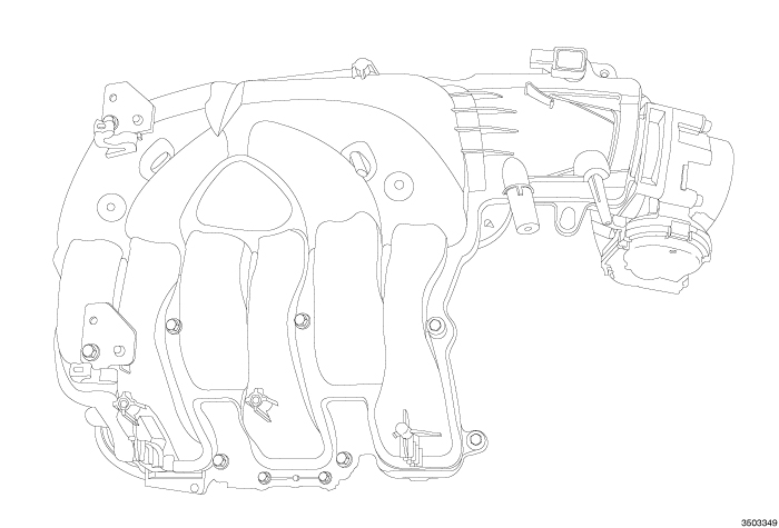 |
The upper intake manifold is an injection molded nylon composite design. The upper intake manifold is sealed to the lower intake manifold using six individual press-in-place port silicone gaskets. Replace the gaskets whenever the upper intake manifold is removed from the engine. There are silencer pads positioned at the rear of the intake manifold and between the upper and lower intake manifolds for improved noise, vibration and harshness (NVH). The left cylinder head cover has two alignment posts to aid proper installation of the silencer pad and there are two brackets bolted to the intake manifold to provide attachment points for the rear silencer pad. The seven upper intake manifold fasteners thread directly into the composite lower intake manifold and are a self-taping design. If the upper intake manifold is damaged or cracked, it must be replaced.
The Electronic Throttle Control (ETC) and Manifold Air Pressure
(MAP) sensor are attached directly to the upper intake manifold. The
upper intake manifold also provides vacuum ports for brake booster,
positive crankcase ventilation (PCV) and emissions control.
Lower Intake Manifold
If the engine has experienced a catastrophic failure, THE INTAKE MANIFOLD MUST BE REPLACED!
CAUTION:
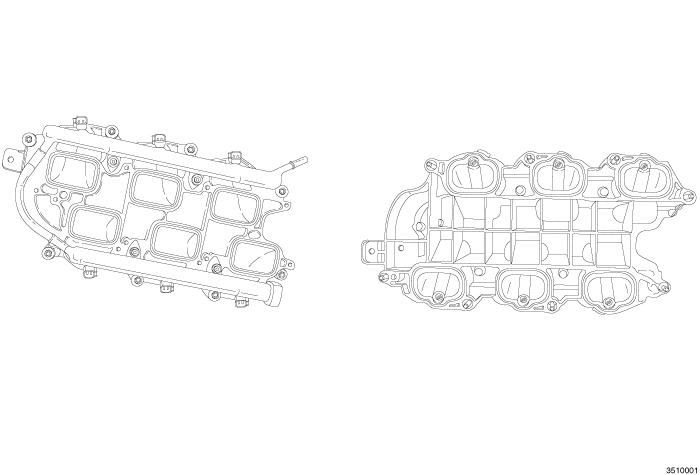 |
The lower intake manifold is an injection molded nylon composite design. The lower intake manifold is sealed to the cylinder heads using six individual press-in-place port silicone gaskets. Replace the gaskets whenever the lower intake manifold is removed from the engine. The seven upper intake manifold fasteners thread directly into the composite lower intake manifold and are a self-taping design.
The fuel injection fuel rail is also a composite design. The four fuel rail fasteners thread directly into the composite lower intake manifold and are a self-taping design. The lower intake manifold can be serviced without removing the fuel injector rail. The fuel rail and fuel injectors must be installed into the lower intake manifold as an assembly. Do not attempt to install the fuel rail when the injectors are in the manifold. Always install new O-rings on the fuel injectors.
If the lower intake manifold is damaged or cracked, it must be
replaced.
DIAGNOSIS AND TESTING - INTAKE MANIFOLD LEAKS
DIAGNOSIS AND TESTING - INTAKE MANIFOLD LEAKS
An intake manifold air leak is characterized by lower than normal manifold vacuum. Also, one or more cylinders may not be functioning.
Use extreme caution when the engine
is operating. Do not stand in a direct line with the fan. Do not put
your hands near the pulleys, belts or the fan. Do not wear loose clothing.
WARNING:
UPPER
UPPER
 |
- Disconnect and isolate the negative battery cable.
-
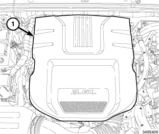
Remove the engine cover (1).
-
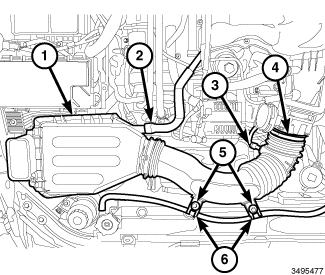
Remove the air cleaner body (1) (Refer to 09 - Engine/Air Intake System/BODY, Air Cleaner - Removal)
.
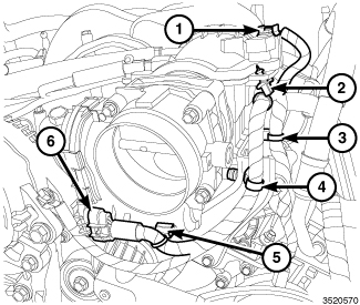
- Disconnect the electrical connectors from the Manifold Absolute Pressure (MAP) sensor (1) and the Electronic Throttle Control (ETC) (6).
- Disengage the ETC harness from the clip (5) on the throttle body.
- Disengage the wire harness retainer (2) from the upper intake manifold.
-
Disengage the wire harness retainers (3 and 4) from the left front upper intake manifold support bracket and reposition the wire harness.
-
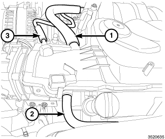
Disconnect the following hoses from the upper intake manifold:
-
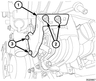
Remove two nuts (2), two bolts (3) and the left front upper intake manifold support bracket (1).
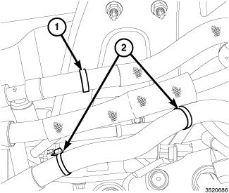
- Disengage the brake booster hose retainer (1) from the left rear upper intake manifold support bracket.
-
Disengage the wire harness retainers (2) from the left rear upper intake manifold support bracket and reposition the wire harness.
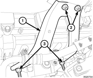
- Remove two nuts (2) from the left rear upper intake manifold support bracket (1).
- Raise and support the vehicle (Refer to 04 - Vehicle Quick Reference/Hoisting - Standard Procedure) .
- Remove the left front wheelhouse inner splash shield (Refer to 23 - Body/Exterior/SHIELD, Splash - Removal) .
-
Loosen two studbolts (3) and reposition the left rear upper intake manifold support bracket (1) away from the upper intake manifold.
- Lower the vehicle.
- Disengage and reposition the following hoses from the upper intake manifold:
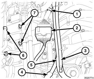
- Disengage the wire harness retainer (1) from the upper intake manifold.
- Disengage the wire harness connector retainer (2) from the right upper intake manifold support bracket.
- Disengage two purge tube retainers (6) from the right upper intake manifold support bracket.
-
Remove two nuts (7) and reposition the heater core coolant tube assembly.
NOTE: Heater core coolant tube assembly not shown for clarity.
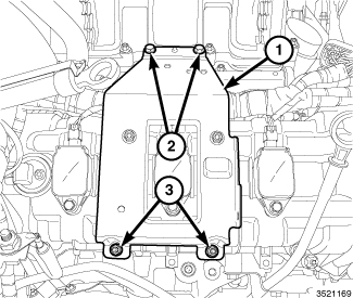
- Remove two bolts (2) from the right upper intake manifold support bracket (1).
- Raise and support the vehicle (Refer to 04 - Vehicle Quick Reference/Hoisting - Standard Procedure) .
- Remove the right front wheelhouse inner splash shield (Refer to 23 - Body/Exterior/SHIELD, Splash - Removal) .
-
Remove two nuts (3) and the right upper intake manifold support bracket (1).
NOTE: The upper intake manifold attaching bolts are captured in the upper intake manifold. Once loosened, the bolts will have to be lifted out of the lower intake manifold and held while removing the upper intake manifold.
NOTE: Exercise care not to inadvertently loosen the two fuel rail attachment bolts that are in close proximity of the upper intake manifold attaching bolts.
-
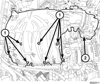
Remove seven upper intake manifold attaching bolts (1) and remove the upper intake manifold (2).
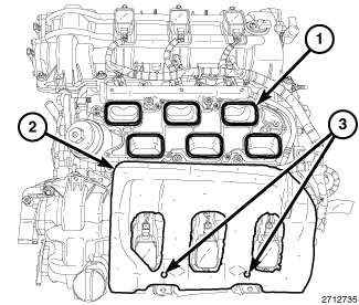
- Remove and discard the six upper to lower intake manifold seals (1).
- Cover the open intake ports to prevent debris from entering the engine.
-
If required, remove the insulator (2) from the LH cylinder head cover.
-
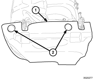
If required, remove the push-pins (2) and the rear insulation pad (1) from the upper intake manifold.
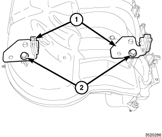
- If required, remove the bolts (2) and the brackets (1) from the upper intake manifold.
- If required, remove the Manifold Air Pressure (MAP) sensor from the upper intake manifold (Refer to 14 - Fuel System/Fuel Injection/SENSOR, Manifold Air Pressure (MAP) - Removal).
-
If required, remove the throttle body from the upper intake manifold (Refer to 14 - Fuel System/Fuel Injection/THROTTLE BODY - Removal)
.
LOWER
LOWER
|
The fuel system is under constant
pressure even with engine off. Before servicing the fuel rail, fuel
system pressure must be released.
WARNING:
- Release fuel system pressure (Refer to 14 - Fuel System/Fuel Delivery - Standard Procedure) .
- Disconnect and isolate the negative battery cable.
-
Remove the air cleaner body and upper intake manifold (2) (Refer to 09 - Engine/Manifolds/MANIFOLD, Intake - Removal)
.
-
Remove the insulator (2) from the LH cylinder head cover.
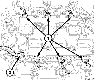
- Disconnect the fuel supply hose (2) from the fuel rail (Refer to 14 - Fuel System/Fuel Delivery/FITTING, Quick Connect - Standard Procedure) .
-
Disconnect the fuel injector electrical connectors (1).
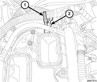
- Disengage the injection/ignition harness retainer (1) form the rear of the lower intake manifold.
-
Disengage the main wire harness retainer (2) form the rear of the lower intake manifold.
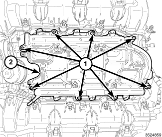
- Remove the eight lower intake manifold attaching bolts (1).
-
Remove the lower intake manifold (2) with the fuel injectors and fuel rail.
-
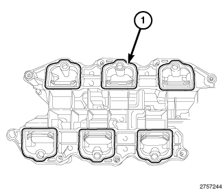
Remove and discard the six lower intake manifold to cylinder head seals (1).
-
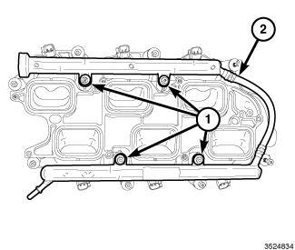
If required, remove the fuel rail (2) and fuel injectors from the lower intake manifold (Refer to 14 - Fuel System/Fuel Delivery/RAIL, Fuel - Removal)
.
INSPECTION
INSPECTION
 |
| NOTE: |
When the upper intake manifold (3) and lower intake manifold (1) are not aligned properly, cross threading of the upper intake manifold attaching bolts can occur. The graphic shows non-repairable damage to the lower intake manifold (1) due to cross threading of an upper intake manifold attaching bolt (2). |
Check both the upper and lower intake manifolds for:
Check the lower intake manifold for:
If either the upper or lower manifold exhibits any damaged or warped conditions, replace the manifold.
UPPER
UPPER
|
- If removed, install the throttle body to the upper intake manifold (Refer to 14 - Fuel System/Fuel Injection/THROTTLE BODY - Installation) .
- If removed, install the Manifold Air Pressure (MAP) sensor to the upper intake manifold (Refer to 14 - Fuel System/Fuel Injection/SENSOR, Manifold Air Pressure (MAP) - Installation).
-
If removed, install the the brackets (1) to the upper intake manifold with bolts (2) tightened to 8 N·m (71 in. lbs.).
-
If removed, install the rear insulation pad (1) with push-pins (2) to the upper intake manifold.
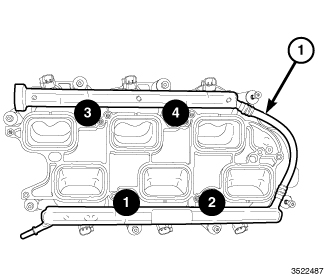
NOTE: Prior to installing the upper intake manifold, verify that the four fuel rail bolts were not inadvertently loosened. The bolts must tightened in the sequence shown to 7 N·m (62 in. lbs.) (Refer to 14 - Fuel System/Fuel Delivery/RAIL, Fuel - Installation) .
-
Clean and inspect the sealing surfaces. Install new upper to lower intake manifold seals (1).
NOTE: Make sure the fuel injectors and wiring harnesses are in the correct position so that they don't interfere with the upper intake manifold installation.
-
If removed, install the insulator (2) to the two alignment posts (3) on top of the LH cylinder head cover.
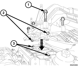
- Lift and hold the seven upper intake attaching bolts (1) clear of the mating surface. Back the bolts out slightly or if required, use an elastic band to hold the bolts clear of the mating surface.
-
Position the upper intake manifold (1) onto the lower intake manifold so that the two locating posts (2) on the upper intake manifold align with corresponding holes (3) in the lower intake manifold.
-
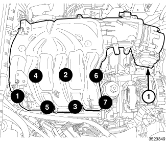
Install the seven upper intake manifold attaching bolts. Tighten the bolts in the sequence shown to 8 N·m (71 in. lbs.).
NOTE: Heater core coolant tube assembly not shown for clarity.
- Install the right upper intake manifold support bracket (1) with two bolts (2) tightened to 8 N·m (71 in. lbs.).
- Raise and support the vehicle (Refer to 04 - Vehicle Quick Reference/Hoisting - Standard Procedure) .
- Install two nuts (3) to the right upper intake manifold support bracket (1) and tighten to 10 N·m (89 in. lbs.).
-
Install the right front wheelhouse inner splash shield (Refer to 23 - Body/Exterior/SHIELD, Splash - Installation)
.
- Lower the vehicle.
- Install the heater core coolant tube assembly with two nuts (7) tightened to 10 N·m (89 in. lbs.).
- Engage two purge tube retainers (6) to the right upper intake manifold support bracket.
- Engage the wire harness retainer (1) to the upper intake manifold.
- Engage the wire harness connector retainer (2) to the right upper intake manifold support bracket.
-
Engage the following hoses to the upper intake manifold:
- Install the left rear upper intake manifold support bracket (1) with two nuts (2) tightened to 10 N·m (89 in. lbs.).
- Raise and support the vehicle (Refer to 04 - Vehicle Quick Reference/Hoisting - Standard Procedure) .
- Install two studbolts (3) to the left rear upper intake manifold support bracket (1) and tighten to 20 N·m (177 in. lbs.).
-
Install the left front wheelhouse inner splash shield (Refer to 23 - Body/Exterior/SHIELD, Splash - Installation)
.
- Lower the vehicle.
- Position the wire harness and engage the wire harness retainers (2) to the left rear upper intake manifold support bracket.
-
Engage the brake booster hose retainer (1) to the left rear upper intake manifold support bracket.
-
Install the left front upper intake manifold support bracket (1) with two nuts (2) and two bolts (3). Tighten the nuts (2) to 10 N·m (89 in. lbs.) and tighten the bolts (3) to 10 N·m (89 in. lbs.).
-
Connect the following hoses to the upper intake manifold:
- Position the wire harness and connect the electrical connectors to the Manifold Absolute Pressure (MAP) sensor (1) and the Electronic Throttle Control (ETC) (6).
- Engage the ETC harness to the clip (5) on the throttle body.
- Engage the wire harness retainer (2) to the upper intake manifold.
-
Engage the wire harness retainers (3 and 4) to the left front upper intake manifold support bracket.
-
Install the air cleaner body (1) (Refer to 09 - Engine/Air Intake System/BODY, Air Cleaner - Installation)
.
- Install the engine cover (1).
-
Connect the negative battery cable and tighten nut to 5 N·m (45 in. lbs.).
LOWER
LOWER
|
-
Clean and inspect the sealing surfaces. Install new lower intake manifold to cylinder head seals (1).
-
If removed, install the fuel injectors and the fuel rail (1) to the lower intake manifold. Tighten the four bolts in the sequence shown to 7 N·m (62 in. lbs.) (Refer to 14 - Fuel System/Fuel Delivery/RAIL, Fuel - Installation)
.
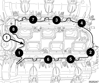
- Position the lower intake manifold (1) on the cylinder head surfaces.
-
Install the manifold attaching bolts and tighten in the sequence shown to 8 N·m (71 in. lbs.).
- Engage the main wire harness retainer (2) to the rear of the lower intake manifold.
-
Engage the injection/ignition harness retainer (1) to the rear of the lower intake manifold.
- Connect the fuel injector electrical connectors (1).
-
Connect the fuel supply hose (2) to the fuel rail (Refer to 14 - Fuel System/Fuel Delivery/FITTING, Quick Connect - Standard Procedure)
-
Install the insulator (2) to the two alignment posts (3) on top of the LH cylinder head cover.
- Install the upper intake manifold (1), support brackets and air cleaner body (Refer to 09 - Engine/Manifolds/MANIFOLD, Intake - Installation)
- Connect the negative battery cable and tighten nut to 5 N·m (45 in. lbs.).
-
Start the engine and check for leaks.