SHOES, Parking Brake
DESCRIPTION
DESCRIPTION
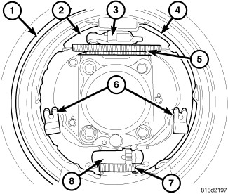 |
Drum in hat park brakes are dual shoe (2AND4), internal expanding units with an automatic self adjusting mechanism.
OPERATION
OPERATION
When the parking brake lever is pulled the brake cable pulls the brake shoes outward against the brake drum. When the brake lever is released the return springs attached to the brake shoes pull the shoes back to their original position.
ROTOR REMOVED
ROTOR REMOVED
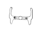
Under normal circumstances, the only time adjustment is required is when the shoes are replaced, removed for access to other parts, or when one or both rotors are replaced.
Adjustment can be made with a standard brake gauge or with adjusting tool. Adjustment is performed with the complete brake assembly installed on the backing plate.
Before adjusting the park brake
shoes be sure that the park brake pedal is in the fully released position.
If park brake pedal is not in the fully released position, the park
brake shoes can not be accurately adjusted.
CAUTION:
- Raise vehicle.
- Remove tire and wheel.
- Remove disc brake caliper from caliper adapter (Refer to 05 - Brakes/Hydraulic/Mechanical/CALIPER, Disc Brake - Removal) .
-
Remove rotor from the
axleshaft (Refer to 05 - Brakes/Hydraulic/Mechanical/ROTOR,
Brake - Removal)
.
NOTE: When measuring the brake drum diameter, the diameter should be measured in the center of the area in which the park brake shoes contact the surface of the brake drum.
-
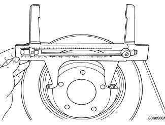
Using Brake Shoe Gauge,
Special Tool C-3919 , or equivalent, accurately measure the inside diameter of the park brake drum
portion of the rotor.
-
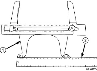
Using a ruler that
reads in 64th of an inch, accurately read the measurement of the inside
diameter of the park brake drum from the special tool.
-
Reduce the inside diameter
measurement of the brake drum that was taken using Special Tool C-3919 by 1/64 of an inch. Reset Gauge, Brake Shoe, Special Tool C-3919 or the equivalent used, so that the outside measurement jaws
are set to the reduced measurement.
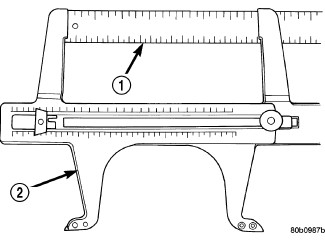
- Place Gauge, Brake Shoe, Special Tool C-3919 , or equivalent over the park brake shoes. The special tool must be located diagonally across at the top of one shoe and bottom of opposite shoe (widest point) of the park brake shoes.
- Using the star wheel adjuster, adjust the park brake shoes until the lining on the park brake shoes just touches the jaws on the special tool.
- Repeat step 8 above and measure shoes in both directions.
- Install brake rotor on the axleshaft (Refer to 05 - Brakes/Hydraulic/Mechanical/ROTOR, Brake - Installation) .
- Rotate rotor to verify that the park brake shoes are not dragging on the brake drum. If park brake shoes are dragging, remove rotor and back off star wheel adjuster one notch and recheck for brake shoe drag against drum. Continue with the previous step until brake shoes are not dragging on brake drum.
- Install disc brake caliper on caliper adapter (Refer to 05 - Brakes/Hydraulic/Mechanical/CALIPER, Disc Brake - Installation) .
- Install wheel and tire.
- Tighten the wheel mounting nuts in the proper sequence until all nuts are torqued to half the specified torque. Then repeat the tightening sequence to the full specified torque of 129 N·m (95 ft. lbs.).
-
Lower vehicle.
CAUTION: Before moving vehicle, pump brake pedal several times to ensure the vehicle has a firm enough pedal to stop the vehicle.
NOTE: After parking brake lining replacement, it is recommended that the parking brake system be conditioned prior to use. This is done by making one stop from 25 mph on dry pavement or concrete using light to moderate force on the parking brake hand lever.
- Road test the vehicle to ensure proper function of the vehicle's brake system.
ROTOR INSTALLED
ROTOR INSTALLED
Adjustment can be made with a standard brake gauge or with adjusting tool. Adjustment is performed with the complete brake assembly installed on the backing plate.
- Be sure parking brake lever is fully released.
- Raise vehicle so rear wheels can be rotated freely.
- Remove plug from each access hole in brake support plates.
- Loosen parking brake cable adjustment nut until there is slack in front cable.
-
Insert adjusting tool
through support plate access hole and engage tool in teeth of adjusting
screw star wheel
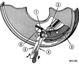
- Rotate adjuster screw star wheel (move tool handle upward) until slight drag can be felt when wheel is rotated.
- Push and hold adjuster lever away from star wheel with thin screwdriver.
- Back off adjuster screw star wheel until brake drag is eliminated.
- Repeat adjustment at opposite wheel. Be sure adjustment is equal at both wheels.
- Install support plate access hole plugs.
- Adjust parking brake cable and lower vehicle.
- Depress park brake lever and make sure park brakes hold the vehicle staionary.
- Release park brake lever.
REMOVAL
REMOVAL
- Raise and support the vehicle.
- Remove the tire and wheel assembly.
- Remove the disc brake caliper adapter (Refer to 05 - Brakes/Hydraulic/Mechanical/ADAPTER, Disc Brake Caliper - Removal) .
-
Remove the disc brake rotor, (Refer to 05 - Brakes/Hydraulic/Mechanical/ROTOR, Brake - Removal)
.
-
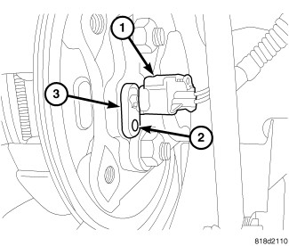
Remove the wheel speed sensor (3) (Refer to 05 - Brakes/Electrical/SENSOR, Wheel Speed - Removal)
.
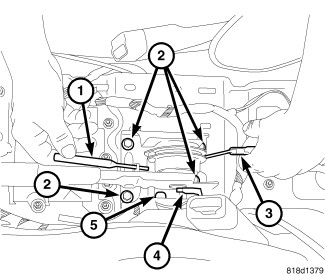
- Remove the center floor console (Refer to 23 - Body/Interior/CONSOLE, Center - Removal) .
-
Lock out the park brake system at the lever using a suitable tool (1) and pulling upward on the brake cable (3) (Refer to 05 - Brakes/Parking Brake - Standard Procedure)
.
-
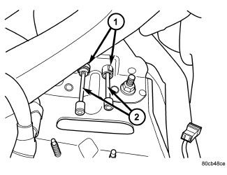
Remove the rear parking brake cables (2) from the equalizer.
-
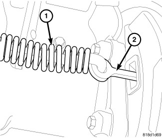
Remove the parking brake cable (1) from the brake shoe lever (2) at the axle.
-
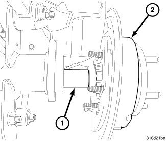
Remove the axle shaft (1), refer to Section 03 - Differential and Driveline/Rear Axle/SHAFT, Axle - Removal.
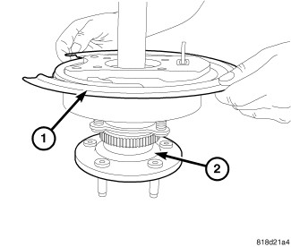
- Tap the seal plate from the brake support (1) on the axle shaft (2).
-
Remove the support plate with the brake shoes (1) from the axle shaft (1).
-
Disassemble the rear park brake shoes.
CLEANING
CLEANING
Clean the individual brake components, including the support plate exterior, with a water dampened cloth or with brake cleaner. Do not use any other cleaning agents. Remove light rust and scale from the brake shoe contact pads on the support plate with fine sandpaper.
INSPECTION
INSPECTION
|
As a general rule, riveted brake shoes should be replaced when worn to within 0.78 mm (1/32 in.) of the rivet heads. Bonded lining should be replaced when worn to a thickness of 1.6 mm (1/16 in.).
Examine the lining contact pattern to determine if the shoes are bent or the drum is tapered. The lining should exhibit contact across its entire width. Shoes exhibiting contact only on one side should be replaced and the drum checked for runout or taper.
Inspect the adjuster screw assembly (8). Replace the assembly if the star wheel or threads are damaged, or the components are severely rusted or corroded.
Discard the brake springs (5AND7) and retainer components (6) if worn, distorted or collapsed. Also replace the springs if a brake drag condition had occurred. Overheating will distort and weaken the springs.
Inspect the brake shoe contact pads on the support plate (1), replace the support plate if any of the pads are worn or rusted through. Also replace the plate if it is bent or distorted.
INSTALLATION
INSTALLATION
| NOTE: |
After parking brake lining replacement, it is recommended that the parking brake system be conditioned prior to use. This is done by making one stop from 25 mph on dry pavement or concrete using light to moderate force on the parking brake lever. |
|
-
Reassemble the rear park brake shoes.
-
Install the support plate (1) on the axle shaft (2).
-
Install the axle shaft (1) to the axle housing, refer to Section 03 - Differential and Driveline/Rear Axle/SHAFT, Axle - Installation.
-
Reconnect the brake cable (1) to the park brake shoe lever (2) behind the support plate.
- Install the rear wheel speed sensor (3). (Refer to 05 - Brakes/Electrical/SENSOR, Wheel Speed - Installation) .
- Adjust the rear brake shoes (Refer to 05 - Brakes/Parking Brake/SHOES, Parking Brake - Adjustments) .
- Install the disc brake rotor (Refer to 05 - Brakes/Hydraulic/Mechanical/ROTOR, Brake - Installation) .
- Install the disc brake caliper adapter. (Refer to 05 - Brakes/Hydraulic/Mechanical/ADAPTER, Disc Brake Caliper - Installation) .
- Install the tire and wheel assembly (Refer to 22 - Tires and Wheels/Wheels - Standard Procedure) .
-
Lower the vehicle.
-
Install the rear park brake cables (2) at the equalizer.
- Remove the lockout (1) on the front park brake lever.
- Check the operation of the park brake system.
-
Install the center floor console (Refer to 23 - Body/Interior/CONSOLE, Center - Installation)
.