8Q - Vehicle Theft Security
- VEHICLE THEFT SECURITY SYSTEM
- SENTRY KEY IMMOBILIZER SYSTEM
- VEHICLE THEFT ALARM
- VEHICLE THEFT SECURITY SYSTEM
- SENTRY KEY IMMOBILIZER SYSTEM
- VEHICLE THEFT ALARM
- DIAGNOSIS AND TESTING - VEHICLE THEFT SECURITY SYSTEM
- DIAGNOSIS AND TESTING - SENTRY KEY IMMOBILIZER SYSTEM
- DIAGNOSIS AND TESTING - VEHICLE THEFT ALARM
- SENTRY KEY IMMOBILIZER SYSTEM INITIALIZATION
- SENTRY KEY TRANSPONDER PROGRAMMING
- SPECIFICATIONS
VEHICLE THEFT SECURITY SYSTEM
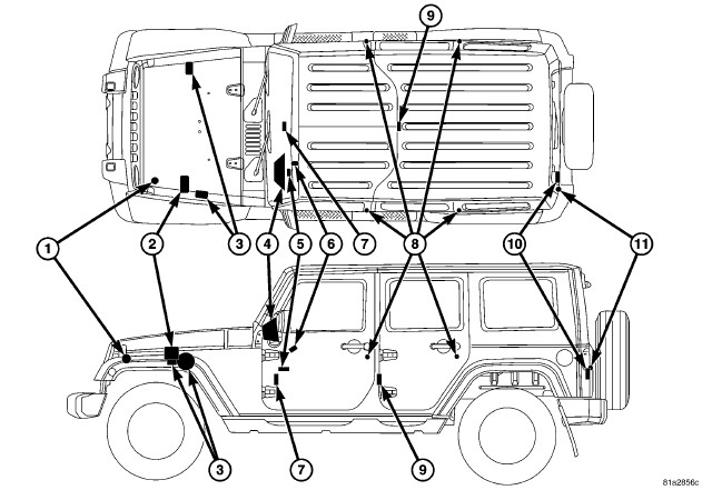 |
The Vehicle Theft Security System (VTSS) is an available factory-installed feature on this vehicle. The VTSS is comprised of two primary subsystems: the optional Vehicle Theft Alarm (VTA) and the standard Sentry Key Immobilizer System (SKIS). The VTA is an active system that provides visual and audible responses as deterrents to and warnings of unauthorized vehicle tampering. The SKIS is a passive system that effectively immobilizes the vehicle against unauthorized operation. Additional details of each of these subsystems and their components can be found elsewhere within this service information.
Certain functions and features of the VTSS rely upon resources shared with or controlled by other electronic modules in the vehicle over the Controller Area Network (CAN) data bus. Other modules that may affect VTSS operation are:
- ElectroMechanical Instrument Cluster - The Instrument Cluster, also known as the Cab Compartment Node (CCN) provides security indicator control (Refer to 08 - Electrical/8J - Instrument Cluster - Description) .
- Powertrain Control Module - The Powertrain Control Module (PCM) provides the SKIS engine control logic.
- Totally Integrated Power Module (2) - The Totally Integrated Power Module (TIPM) is located in the engine compartment, near the battery. The TIPM monitors door, swing gate and hood ajar switch status and provides the VTA system logic (Refer to 08 - Electrical/8E - Electronic Control Modules/MODULE, Totally Integrated Power (TIPM) - Description).
Except for the Sentry Key transponders, which rely upon Radio Frequency (RF) communication, hard wired circuitry connects the VTA and SKIS components to the electrical system of the vehicle. These hard wired circuits are integral to several wire harnesses, which are routed throughout the vehicle and retained by many different methods. These circuits may be connected to each other, to the vehicle electrical system and to the SKIS components through the use of a combination of soldered splices, splice block connectors, and many different types of wire harness terminal connectors and insulators. Refer to the appropriate wiring information. The wiring information includes wiring diagrams, proper wire and connector repair procedures, further details on wire harness routing and retention, as well as pin out and location views for the various wire harness connectors, splices and grounds.
SENTRY KEY IMMOBILIZER SYSTEM
The Sentry Key Immobilizer System (SKIS) is standard factory-installed equipment on this vehicle. The SKIS provides passive vehicle protection by preventing the engine from operating unless a valid electronically encoded key is detected in the ignition lock cylinder.
The SKIS includes the following major components, which are described in further detail elsewhere in this service information:
- Security Indicator - A security indicator is integral to the Instrument Cluster, also known as the Cab Compartment Node (CCN). (Refer to 08 - Electrical/8J - Instrument Cluster - Description) .
- Sentry Key Remote Entry Module (6) - The Sentry Key Remote Entry Module (SKREEM), also known as the Wireless Control Module (WCM) is located on the right side of the steering column near the ignition lock cylinder housing and an integral molded plastic antenna ring circles the ignition lock cylinder like a halo. The SKREEM and its antenna are concealed beneath the shrouds on the steering column. (Refer to 08 - Electrical/8Q - Vehicle Theft Security/MODULE, Sentry Key Immobilizer (SKREEM) - Description).
- Sentry Key Transponder - The Sentry Key transponder is contained within the Remote Keyless Entry (RKE) transmitter integral to the head of the ignition key. (Refer to 08 - Electrical/8Q - Vehicle Theft Security/KEY, Transponder - Description) .
VEHICLE THEFT ALARM
The VTA is available in two different configurations for this vehicle: One configuration is designed for vehicles manufactured for sale in North America; while, the other configuration is designed for vehicles manufactured for sale in markets outside of North America, also referred to as export markets within the context of this service information. In addition, the VTA for export is available in two versions: base and premium. All vehicles equipped with VTA are also equipped with the Remote Keyless Entry (RKE) system and the Sentry Key Immobilizer System (SKIS), regardless of their market destination.
The North American and export base version of the VTA system provide perimeter vehicle protection by monitoring the vehicle doors, the ignition switch, the swing gate and, for vehicles built for certain markets where it is required equipment, the hood. If unauthorized vehicle use or tampering is detected, these systems respond by pulsing the vehicle horn as an audible deterrent and flashing certain exterior lamps as a visual deterrent.
The export premium version of the VTA system is only available in vehicles manufactured for sale in certain markets where it is required equipment. The export premium version of the VTA provides the same perimeter protection features as the base version, but adds interior vehicle intrusion protection. The export premium VTA also enhances the pulsing horn feature of the base version with an alarm siren as the audible deterrent, while retaining the flashing exterior lamps as the visual deterrent.
The VTA includes the following major components, which are described in further detail elsewhere in this service information:
- Door Ajar Switches (8) - A door ajar switch is integral to the door latch mechanism of each front and rear door. (Refer to 23 - Body/Decklid/Hatch/Liftgate/Tailgate/LATCH - Removal) .
- Hood Ajar Switch (1) - A hood ajar switch is located in a bracket on the inboard side of the left front fender load path beam within the engine compartment of vehicles built for sale in certain export markets where it is required equipment.
- Intrusion Module (5) - An intrusion module is located on a bracket on the lower instrument panel reinforcement beneath the driver side instrument panel in the passenger compartment of vehicles built for sale in certain export markets where it is required equipment.
- Intrusion Sensors (7, 9 and 10) - Two (two-door vehicles) or three (four-door vehicles) microwave intrusion sensors are located within the passenger compartment of vehicles built for sale in certain export markets where it is required equipment. One sensor is located within the lower center stack area of the instrument panel, another is located within the rear of the center floor console (four-door vehicles only) and the third is located within the swing gate.
- Swing Gate Ajar Switch (11) - A swing gate ajar switch is integral to the latch for the swing gate in the vehicle. (Refer to 23 - Body/Decklid/Hatch/Liftgate/Tailgate/LATCH - Removal) .
- Security Indicator (4) - A security indicator is integral to the Instrument Cluster, also known as the Cab Compartment Node (CCN). (Refer to 08 - Electrical/8J - Instrument Cluster - Description) .
- Siren (3) - An alarm siren is located on the right component tray (gasoline engine) or on the inboard side of the left front fender load path beam (diesel engine) within the engine compartment of vehicles built for sale in certain export markets where it is required equipment.
VEHICLE THEFT SECURITY SYSTEM
The Vehicle Theft Security System (VTSS) is comprised of two primary subsystems: Sentry Key Immobilizer System (SKIS) and Vehicle Theft Alarm (VTA). Additional operational details on each of these two subsystems of the VTSS can be found elsewhere within this service information.
SENTRY KEY IMMOBILIZER SYSTEM
The Sentry Key Immobilizer System (SKIS) is designed to provide passive protection against unauthorized vehicle use by disabling the engine after about two seconds of running whenever any method other than a valid Sentry Key is used to start the vehicle. The SKIS is considered a passive protection system because it is always active when the ignition system is energized and does not require any customer intervention. The SKIS uses Radio Frequency (RF) communication to obtain confirmation that the key in the ignition switch is a valid key for operating the vehicle. The microprocessor-based SKIS hardware and software also uses electronic messages to communicate with other electronic modules in the vehicle over the Controller Area Network (CAN) data bus. (Refer to 08 - Electrical/8E - Electronic Control Modules/COMMUNICATION - Operation) .
Pre-programmed Sentry Key transponders are provided with the vehicle from the factory. Each Sentry Key REmote Entry Module (SKREEM) (also known as the Wireless Control Module/WCM) will recognize a maximum of eight Sentry Keys. If the customer would like additional keys other than those provided with the vehicle, they may be purchased from any authorized dealer. These additional keys must be programmed to the SKREEM in the vehicle in order for the system to recognize them as valid keys. This can be done by the dealer using a diagnostic scan tool or, if Customer Learn programming is an available SKIS feature in the market where the vehicle was purchased, the customer can program the additional keys, as long as at least two valid Sentry Keys are already available. (Refer to 08 - Electrical/8Q - Vehicle Theft Security - Standard Procedure) .
The SKREEM performs a self-test of the SKIS each time the ignition switch is turned to the ON position, and will store fault information in the form of a Diagnostic Trouble Code (DTC) if a system malfunction is detected. The SKREEM will also send an electronic message to the instrument cluster if a fault is detected, and the ElectroMechanical Instrument Cluster (EMIC) (also known as the Cab Compartment Node/CCN) illuminates the security indicator as appropriate.
The hard wired circuits between components related to the SKIS may be diagnosed using conventional diagnostic tools and procedures. Refer to the appropriate wiring information. The wiring information includes wiring diagrams, proper wire and connector repair procedures, details of wire harness routing and retention, connector pin out information and location views for the various wire harness connectors, splices and grounds.
However, conventional diagnostic methods will not prove conclusive in the diagnosis of the SKIS or the electronic controls and communication between other modules and devices that provide some features of the SKIS. The most reliable, efficient and accurate means to diagnose the SKIS or the electronic controls and communication related to SKIS operation requires the use of a diagnostic scan tool. Refer to the appropriate diagnostic information.
VEHICLE THEFT ALARM
The Totally Integrated Power Module (TIPM) is used on this vehicle to control and integrate many of the functions and features included in the Vehicle Theft Alarm (VTA). In the VTA system, the TIPM receives inputs indicating the status of the door ajar switches, the ignition switch, the swing gate ajar switch and the power lock switches. In vehicles built for certain export markets where it is required, the hood ajar switch also provides a hard wired input to the TIPM and the intrusion module provides electronic message inputs to the TIPM over the Controller Area Network (CAN) data bus. The TIPM processes the information from all of these inputs and sends electronic messages to the ElectroMechanical Instrument Cluster (EMIC) (also known as the Cab Compartment Node/CCN) over the CAN data bus to control the security indicator as appropriate. The TIPM internally controls the output to the hazard warning lamps and sends a control output to energize or de-energize the horn relay as appropriate. On vehicles with an intrusion module, the horn output of the TIPM is replaced by an output of the siren module that is controlled by the intrusion module.
The hard wired circuits between components related to the VTA system may be diagnosed using conventional diagnostic tools and procedures. Refer to the appropriate wiring information. The wiring information includes wiring diagrams, proper wire and connector repair procedures, details of wire harness routing and retention, connector pin out information and location views for the various wire harness connectors, splices and grounds.
However, conventional diagnostic methods will not prove conclusive in the diagnosis of the VTA system or the electronic controls and communication between modules and devices that provide some features of the VTA system. The most reliable, efficient and accurate means to diagnose the VTA system or the electronic controls and communication related to VTA system operation requires the use of a diagnostic scan tool. See the Vehicle Theft Security System menu item on the scan tool. Refer to the appropriate diagnostic information.
Following are paragraphs that briefly describe the operation of each of the VTA features.
OPERATING MODES
Following are paragraphs that briefly describe the operation of each of the Vehicle Theft Alarm (VTA) operating modes.
- Enabling - The TIPM must have the VTA function electronically enabled in order for the VTA to perform as designed. The logic in the TIPM keeps its VTA function dormant until it is enabled using a diagnostic scan tool. The VTA function of the TIPM is enabled on vehicles equipped with the VTA option at the factory, but a service replacement TIPM must be VTA-enabled by the dealer using a diagnostic scan tool. Refer to the appropriate diagnostic information.
- Arming - Passive arming of the VTA occurs when the vehicle is exited with the key removed from the ignition switch, the headlamps are turned Off, and the doors are locked while they are open using the power lock switch. Active arming occurs when the Lock button on the Remote Keyless Entry (RKE) transmitter is depressed to lock the vehicle. For active arming to occur, the doors must be closed and the ignition switch must be in the Off position when the RKE transmitter Lock button is depressed. The power lock switch will not function if the key is in the ignition switch or the headlamps are turned On with the driver side front door open. Pre-arming of the VTA is initiated when a door is open when the vehicle is locked using a power door lock switch or when the RKE transmitter Lock button is depressed. Pre-arming will not occur if the key is in the ignition switch or the headlamps are turned On with the driver side front door open. When the VTA is pre-armed, the arming sequence is delayed until all of the doors have been closed. The VTA will remain in pre-armed mode for up to 16 seconds after all doors have been closed. Once the VTA begins the passive or active arming sequence, the security indicator in the instrument cluster will flash rapidly for about 16 seconds. This indicates that VTA arming is in progress. If the ignition switch is turned to the On position, if a door or the swing gate is unlocked or opened by any means, or if the RKE Panic button (if equipped) is depressed during the 16 second arming process, the security indicator will stop flashing and the arming process will abort. Once the arming sequence is successfully completed, the security indicator will flash at a slower rate, indicating that the VTA is armed. For the swing gate and the hood of vehicles equipped with the hood ajar switch, the VTA arming sequence will occur regardless of whether the swing gate or the hood is open or closed, but the security indicator will illuminate solid and the swing gate or under hood area will not be protected until the swing gate or the hood is closed. Also, if the status of the swing gate ajar or the hood ajar switch changes from open to closed during the 16 second arming process, the security indicator will switch from solid to flashing and the VTA arming sequence will abort. Once the arming process is successfully completed, the security indicator will flash at a slower rate, indicating that the VTA is armed.
- Disarming - For vehicles built for the North American market, passive disarming of the VTA occurs by inserting a valid Sentry Key Immobilizer System (SKIS) key into the ignition lock cylinder or by turning the ignition switch to the On position. Active disarming of the VTA for all markets occurs when the vehicle is unlocked by depressing the Unlock button of the RKE transmitter. Once the alarm has been activated, either disarming method will also deactivate the alarm. Depressing the Panic button (if equipped) on the RKE transmitter will not disarm the VTA.
- Alarm - The VTA alarm output varies by the version of the VTA with which the vehicle is equipped. In all cases, the alarm provides both visual and audible outputs; however, the time intervals of these outputs vary by the requirements of the market for which the vehicle is manufactured. In all cases, the visual output will be a flashing On and Off of the exterior lamps. For vehicles equipped with the North American or the export base version of the VTA, the audible output will be a pulsing of the horn. For vehicles with the export premium version of the VTA, the audible output will be a cycling of the alarm siren in addition to the pulsing horn. The inputs that will trigger the alarm include the ignition switch, the door ajar switches, the swing gate ajar switch and, in vehicles built for certain markets where they are required, the hood ajar switch and the intrusion module.
- Power-Up Mode - When the armed VTA senses that the battery has been disconnected and reconnected, it enters its power-up mode. In the power-up mode, the alarm system remains armed following a battery failure or disconnect. If the VTA was armed prior to a battery disconnect or failure, the technician or vehicle operator will have to actively or passively disarm the alarm system after the battery is reconnected. The power-up mode will also apply if the battery goes dead while the system is armed, and battery jump-starting is attempted. The VTA will be armed until the technician or vehicle operator has actively or passively disarmed the alarm system. If the VTA is in the disarmed mode prior to a battery disconnect or failure, it will remain disarmed after the battery is reconnected or replaced, or if jump-starting is attempted.
- Tamper Alert - The VTA tamper alert feature will pulse the horn three times upon VTA disarming if the alarm was triggered and has since timed out. This feature alerts the vehicle operator that the VTA alarm was activated while the vehicle was unattended.
- Intrusion Alarm - The intrusion alarm is an exclusive feature of the export premium version of the VTA, which is only available in certain markets where it is required. When the VTA is armed, the intrusion module uses hard wired outputs to control two (two-door vehicles) or three (four-door vehicles) microwave intrusion sensors which allow the module to monitor the interior of the vehicle for movement. If motion is detected, the intrusion module sends an electronic message to the TIPM over the CAN data bus to invoke the visual alarm features, and sends an electronic message to the alarm siren in the engine compartment over a dedicated serial bus to invoke the audible alarm feature. The motion detect feature of the intrusion module can be disabled by depressing the Lock button on the RKE transmitter 3 times within 15 seconds during VTA arming, while the security indicator is still flashing rapidly. The VTA provides a single short siren chirp as an audible confirmation that the motion detect disable request has been received. The intrusion module must be electronically enabled in order for the intrusion alarm to perform as designed. The intrusion alarm function of the intrusion module is enabled on vehicles equipped with this option at the factory, but a service replacement module must be configured and enabled by the dealer using a diagnostic scan tool. Refer to the appropriate diagnostic information. The intrusion module monitors the condition of the intrusion sensors as well as the siren, and will store fault information in the form of a Diagnostic Trouble Code (DTC) if a system malfunction is detected. The intrusion module may be diagnosed, and any stored DTC can be retrieved using a diagnostic scan tool. Refer to the appropriate diagnostic information.
DIAGNOSIS AND TESTING - VEHICLE THEFT SECURITY SYSTEM
The Vehicle Theft Security System (VTSS) is divided into two basic subsystems: Sentry Key Immobilizer System (SKIS) and Vehicle Theft Alarm (VTA). The recommended procedures for diagnosis and testing of each of these two VTSS subsystems can be found elsewhere within this service information.
DIAGNOSIS AND TESTING - SENTRY KEY IMMOBILIZER SYSTEM
To avoid serious or fatal injury
on vehicles equipped with airbags, disable the Supplemental Restraint
System (SRS) before attempting any steering wheel, steering column,
airbag, seat belt tensioner, impact sensor or instrument panel component
diagnosis or service. Disconnect and isolate the battery negative
(ground) cable, then wait two minutes for the system capacitor to
discharge before performing further diagnosis or service. This is
the only sure way to disable the SRS. Failure to take the proper precautions
could result in accidental airbag deployment.
WARNING:
The hard wired circuits between components related to the SKIS may be diagnosed using conventional diagnostic tools and procedures. Refer to the appropriate wiring information. The wiring information includes wiring diagrams, proper wire and connector repair procedures, details of wire harness routing and retention, connector pin out information and location views for the various wire harness connectors, splices and grounds.
However, conventional diagnostic methods will not prove conclusive in the diagnosis of the SKIS or the electronic controls and communication between other modules and devices that provide some features of the SKIS. The most reliable, efficient and accurate means to diagnose the SKIS or the electronic controls and communication related to SKIS operation requires the use of a diagnostic scan tool. Refer to the appropriate diagnostic information.
| SENTRY KEY IMMOBILIZER SYSTEM DIAGNOSIS | ||
|---|---|---|
| CONDITION | POSSIBLE CAUSES | CORRECTION |
|
SECURITY INDICATOR FAILS TO LIGHT DURING BULB TEST |
1. Ineffective Light-Emitting Diode (LED). |
1. Use a diagnostic scan tool to perform the instrument cluster actuator test. Refer to the appropriate diagnostic information. |
|
2. Ineffective fuse. |
2. Check the SKREEM/WCM fused B(+) fuse and the fused ignition switch output (run-start) fuse in the Totally Integrated Power Module (TIPM). Replace the fuses, if required. |
|
|
3. Ineffective ground circuit. |
3. Test and repair the open ground circuit at the connector for the SKREEM, if required. |
|
|
4. Ineffective battery feed circuit. |
4. Test and repair the open battery feed circuit at the connector for the SKREEM, if required. |
|
|
5. Ineffective ignition feed circuit. |
5. Test and repair the open ignition feed circuit at the connector for the SKREEM, if required. |
|
|
SECURITY INDICATOR FLASHES FOLLOWING BULB TEST |
1. Invalid key in ignition switch lock cylinder. |
1. Replace the key with a known valid key. |
|
2. Key-related fault. |
2. Use a diagnostic scan tool and the appropriate diagnostic information for further diagnosis. |
|
|
SECURITY INDICATOR LIGHTS SOLID FOLLOWING BULB TEST |
1. SKIS system malfunction/fault detected. |
1. Use a diagnostic scan tool and the appropriate diagnostic information for further diagnosis. |
|
2. SKIS system ineffective. |
2. Use a diagnostic scan tool and the appropriate diagnostic information for further diagnosis. |
|
DIAGNOSIS AND TESTING - VEHICLE THEFT ALARM
To avoid serious or fatal injury
on vehicles equipped with airbags, disable the Supplemental Restraint
System (SRS) before attempting any steering wheel, steering column,
airbag, seat belt tensioner, impact sensor or instrument panel component
diagnosis or service. Disconnect and isolate the battery negative
(ground) cable, then wait two minutes for the system capacitor to
discharge before performing further diagnosis or service. This is
the only sure way to disable the SRS. Failure to take the proper precautions
could result in accidental airbag deployment.
WARNING:
The hard wired circuits between components related to the VTA system may be diagnosed using conventional diagnostic tools and procedures. Refer to the appropriate wiring information. The wiring information includes wiring diagrams, proper wire and connector repair procedures, details of wire harness routing and retention, connector pin out information and location views for the various wire harness connectors, splices and grounds.
However, conventional diagnostic methods will not prove conclusive in the diagnosis of the VTA system or the electronic controls and communication between other modules and devices that provide some features of the VTA system. The most reliable, efficient and accurate means to diagnose the VTA system or the electronic controls and communication related to VTA system operation requires the use of a diagnostic scan tool. See the Vehicle Theft Security System menu item on the scan tool. Refer to the appropriate diagnostic information.
SENTRY KEY IMMOBILIZER SYSTEM INITIALIZATION
The Sentry Key Immobilizer System (SKIS) must be initialized following a Sentry Key REmote Entry Module (SKREEM) (also known as the Sentry Key Immobilizer Module/SKIM or the Wireless Control Module/WCM) replacement. SKIS initialization requires the use of a diagnostic scan tool. Initialization will also require that you have access to the unique four-digit PIN code that was assigned to the original SKREEM. The PIN code must be used to enter the Secured Access Mode in the SKREEM. This PIN number may be obtained from the vehicle owner, from the original vehicle invoice, or from the Chrysler Customer Center. (Refer to 08 - Electrical/8E - Electronic Control Modules - Standard Procedure) .
| NOTE: |
If a Powertrain Control Module (PCM) is replaced on a vehicle equipped with the Sentry Key Immobilizer System (SKIS), the unique Secret Key data must be transferred from the Sentry Key REmote Entry Module (SKREEM) (also known as the Sentry Key Immobilizer Module/SKIM or the Wireless Control Module/WCM) to the new PCM using the appropriate programming procedure. This procedure also requires the use of a diagnostic scan tool and the unique four-digit PIN code to enter the Secured Access Mode in the SKREEM. Refer to the appropriate service and diagnostic information for the proper PCM replacement procedure. |
SENTRY KEY TRANSPONDER PROGRAMMING
All Sentry Keys included with the vehicle are pre-programmed to work with the Sentry Key Immobilizer System (SKIS) when it is shipped from the factory. The Sentry Key REmote Entry Module (SKREEM) (also known as the Sentry Key Immobilizer Module/SKIM or the Wireless Control Module/WCM) may be programmed to recognize up to a total of eight Sentry Keys. When programming a blank Sentry Key transponder, the key must first be cut to match the ignition switch lock cylinder in the vehicle for which it will be used. Once the additional or new key has been cut, the SKREEM must be programmed to recognize it as a valid key. There are two possible methods to program the SKREEM to recognize a new or additional valid key, the Secured Access Method and the Customer Learn Method. Following are the details of these two programming methods.
SECURED ACCESS METHOD
The Secured Access method applies to all vehicles. This method requires the use of a diagnostic scan tool. This method will also require that you have access to the unique four-digit PIN code that was assigned to the original SKREEM. The PIN code must be used to enter the Secured Access Mode in the SKREEM. This PIN number may be obtained from the vehicle owner, from the original vehicle invoice, or from the Chrysler Customer Center. (Refer to 08 - Electrical/8E - Electronic Control Modules - Standard Procedure) .
CUSTOMER LEARN METHOD
| NOTE: |
The Customer Learn feature is only available on domestic vehicles, or those vehicles which have a U.S. country code designator. This programming method also requires access to at least two valid Sentry Keys. If two valid Sentry Keys are not available, or if the vehicle does not have a U.S. country code designator, the Secured Access Method MUST be used to program new or additional valid keys to the SKREEM. |
The Customer Learn programming method procedures are as follows:
- Obtain the blank Sentry Key(s) that are to be programmed as valid keys for the vehicle. Cut the blank key(s) to match the ignition switch lock cylinder mechanical key codes.
- Insert one of the two valid Sentry Keys into the ignition switch and turn the ignition switch to the ON position.
- After the ignition switch has been in the ON position for longer than 3 seconds, but no more than 15 seconds, cycle the ignition switch back to the OFF position. Replace the first valid Sentry Key in the ignition switch lock cylinder with the second valid Sentry Key and turn the ignition switch back to the ON position. The second valid Sentry Key must be inserted in the lock cylinder within 15 seconds of removing the first valid key.
- About 10 seconds after the completion of Step #3, the security indicator in the instrument cluster will start to flash and a single audible chime will sound to indicate that the system has entered the Customer Learn programming mode.
- Within 60 seconds of entering the Customer Learn programming mode, turn the ignition switch to the OFF position, replace the valid Sentry Key with a blank Sentry Key transponder, and turn the ignition switch back to the ON position.
- About 10 seconds after the completion of Step #5, a single audible chime will sound and the security indicator will stop flashing, stay ON solid for 3 seconds, then turn OFF to indicate that the blank Sentry Key has been successfully programmed. The SKIS will immediately exit the Customer Learn programming mode. After the ignition is cycled the vehicle may be started using the newly programmed valid Sentry Key.
Each of these steps must be repeated and completed in their entirety for each additional Sentry Key that is to be programmed. If the above steps are not completed in the given sequence, or within the allotted time, the SKIS will exit the Customer Learn programming mode and the programming will be unsuccessful. The SKREEM will also automatically exit the Customer Learn programming mode if it sees a non-blank Sentry Key transponder when it should see a blank, if it has already programmed 8 valid Sentry Keys, or if the ignition switch is turned to the OFF position for more than about 50 seconds.
| NOTE: |
If an attempt is made to start the vehicle while in the Customer Learn mode (security indicator flashing), the SKIS will respond as though the vehicle were being started with an invalid key. In other words, the engine will stall after about two seconds of operation. No faults will be set. |
| NOTE: |
Once a Sentry Key has been programmed as a valid key to a vehicle, it cannot be programmed as a valid key for use on any other vehicle. |
SPECIFICATIONS
| TORQUE SPECIFICATIONS | |||
|---|---|---|---|
| DESCRIPTION | N·m | Ft. Lbs. | In. Lbs. |
|
Hood Ajar Switch Bracket Screw |
8 |
- |
71 |
|
Intrusion Module Mounting Screws |
8 |
- |
71 |
|
SKREEM Mounting Screw |
2 |
- |
20 |
|
Siren Mounting Screws |
8 |
- |
71 |