Cylinder Head
DESCRIPTION
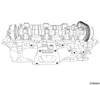 |
The aluminum cylinder heads are a unique design with left and right
castings. The exhaust manifolds are integrated into the cylinder heads.
The cylinder head features four valves per cylinder with pressed in
powdered metal valve guides. The valve guides are not serviceable.
The DOHC valvetrain uses roller rocker arms with hydraulic lifters.
The cylinder head’s camshaft bearing caps are made of powdered metal
and the location and direction of each cap is marked on the side of
the caps. The spark plug tubes are pressed into the cylinder heads
and sealed in place. The tubes are a thin wall design and caution
must be taken when working in the spark plug tube area.
CYLINDER HEAD GASKET

A cylinder head gasket leak can be located between adjacent cylinders or between a cylinder and the adjacent water jacket.
Possible indications of the cylinder head gasket leaking between adjacent cylinders are:
Possible indications of the cylinder head gasket leaking between a cylinder and an adjacent water jacket are:
- Engine overheating
- Loss of coolant
- Excessive steam (white smoke) emitting from exhaust
- Coolant foaming
CYLINDER-TO-CYLINDER LEAKAGE TEST
To determine if an engine cylinder head gasket is leaking between adjacent cylinders, follow the procedures in Cylinder Compression Pressure Test (Refer to 09 - Engine - Diagnosis and Testing) . An engine cylinder head gasket leaking between adjacent cylinders will result in approximately a 50 - 70% reduction in compression pressure.
CYLINDER-TO-WATER JACKET LEAKAGE TEST
USE EXTREME CAUTION WHEN THE ENGINE
IS OPERATING WITH COOLANT PRESSURE CAP REMOVED.
WARNING:
VISUAL TEST METHOD
With the engine cool, remove the coolant pressure cap. Start the engine and allow it to warm up until thermostat opens.
If a large combustion/compression pressure leak exists, bubbles will be visible in the coolant.
COOLING SYSTEM TESTER METHOD
|
WITH THE COOLING SYSTEM TESTER
IN PLACE, PRESSURE WILL BUILD UP FAST. EXCESSIVE PRESSURE BUILT UP
BY CONTINUOUS ENGINE OPERATION MUST BE RELEASED TO A SAFE PRESSURE
POINT. NEVER PERMIT THE PRESSURE TO EXCEED 138 kPa (20 psi).
WARNING:
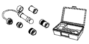
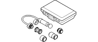
Install Cooling System Tester 7700-A or equivalent to pressure cap neck. Start the engine and observe the tester's pressure gauge. If gauge pulsates with every power stroke of a cylinder a combustion pressure leak is evident.
CHEMICAL TEST METHOD

|
Combustion leaks into the cooling system can also be checked by using Bloc-Chek Kit C-3685-A or equivalent. Perform test following the procedures supplied with the tool kit.
HYDRAULIC LASH ADJUSTER
A tappet-like noise may be produced from several items. Check the following items.
- Engine oil level too high or too low. This may cause aerated oil to enter the adjusters and cause them to be spongy.
- Insufficient running time after rebuilding cylinder head. Low speed running up to 1 hour may be required.
- Turn engine off and let set for a few minutes before restarting. Repeat this several times after engine has reached normal operating temperature.
- Low oil pressure.
- The oil passsage in cylinder head gasket or the oil passage to the cylinder head is plugged with debris.
- Air ingested into oil due to broken or cracked oil pump pick up.
- Worn valve guides.
- Rocker arm ears contacting valve spring retainer.
- Rocker arm loose, adjuster stuck or at maximum extension and still leaves lash in the system.
- Oil leak or excessive cam bore wear in cylinder head.
-
Faulty lash adjuster.
- Check lash adjusters for “sponginess” while installed in cylinder head and cam on camshaft at base circle. Depress part of rocker arm over adjuster. Normal adjusters should feel firm when pressed quickly. When pressed very slowly, lash adjusters should collapse.
- Remove suspected lash adjusters, and replace.
- Before installation, make sure adjusters are full of oil. This can be verified by little plunger travel when lash adjuster is depressed quickly.
LEFT
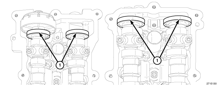 |
The magnetic timing wheels (1)
must not come in contact with magnets (pickup tools, trays, etc.)
or any other strong magnetic field. This will destroy the timing wheels
ability to correctly relay camshaft position to the camshaft position
sensor.
CAUTION:
 |
- Perform the fuel pressure release procedure (Refer to 14 - Fuel System/Fuel Delivery - Standard Procedure) .
- Disconnect and isolate the negative battery cable.
-
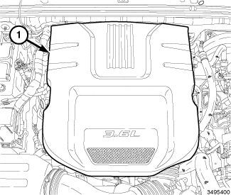
Remove the engine cover (1).
-
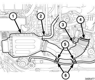
Remove the air cleaner body (1) (Refer to 09 - Engine/Air Intake System/BODY, Air Cleaner - Removal)
.
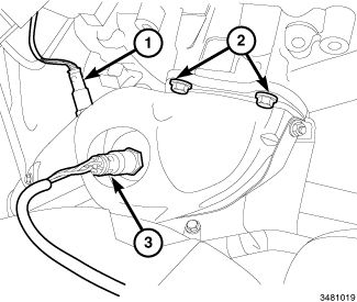
NOTE: Right catalytic converter shown, left catalytic converter similar.
- Raise and support the vehicle (Refer to 04 - Vehicle Quick Reference/Hoisting - Standard Procedure) .
- Drain the cooling system (Refer to 07 - Cooling - Standard Procedure) .
- Drain the engine oil (Refer to 09 - Engine/Lubrication/OIL - Standard Procedure) .
- Disconnect the left upstream (3) and downstream (1) oxygen sensor connectors from the main wire harness.
-
Remove the left catalytic converter (Refer to 11 - Exhaust System/CONVERTER, Catalytic - Removal)
.
- Lower the vehicle.
-
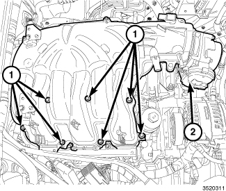
Remove the upper and lower intake manifolds (2) and insulator (Refer to 09 - Engine/Manifolds/MANIFOLD, Intake - Removal)
- Remove the right and left cylinder head covers (Refer to 09 - Engine/Cylinder Head/COVER(S) , Cylinder Head - Removal).
-
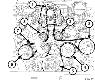
Remove the accessory drive belt (7) (Refer to 07 - Cooling/Accessory Drive/BELT, Serpentine - Removal)
-
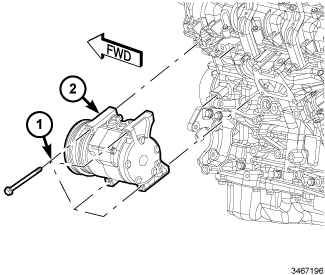
Remove the four bolts (1) and reposition the A/C compressor (2).
-
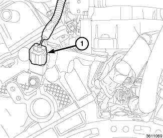
Disconnect the ignition coil capacitor electrical connector (1).
-
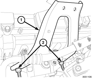
Remove the two studbolts (3) and remove the left rear upper intake manifold support bracket (1).
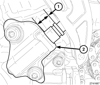
- Remove the spark plugs (Refer to 08 - Electrical/8I - Ignition Control/SPARK PLUG - Removal) .
-
Remove the upper oil pan, crankshaft vibration damper and engine timing cover (Refer to 09 - Engine/Valve Timing/COVER(S)
, Engine Timing - Removal)
NOTE: Take this opportunity to measure timing chain wear (Refer to 09 - Engine/Valve Timing - Standard Procedure) .
-
Lower the vehicle.
CAUTION: When aligning timing marks, always rotate engine by turning the crankshaft. Failure to do so will result in valve and/or piston damage.
-
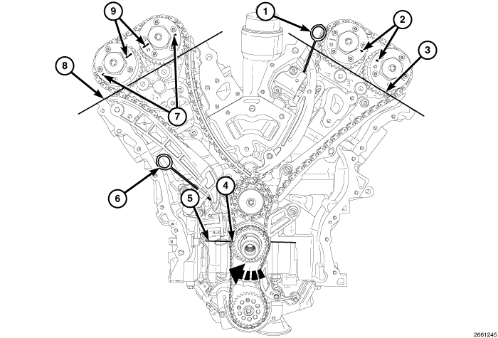
Rotate the crankshaft CW to place the number one piston at TDC on the exhaust stroke by aligning the dimple (4) on the crankshaft with the block/bearing cap junction (5). The left side cam phaser arrows (2) should point toward each other and be parallel to the valve cover sealing surface (3). The right side cam phaser arrows (7) should point away from each other and the scribe lines (9) should be parallel to the valve cover sealing surface (8).
CAUTION: Always reinstall timing chains so that they maintain the same direction of rotation. Inverting a previously run chain on a previously run sprocket will result in excessive wear to both the chain and sprocket.
-
Mark the direction of rotation on the timing chain using a paint pen or equivalent to aid in reassembly.
CAUTION: When the timing chains are removed and the cylinder heads are still installed, DO NOT rotate the camshafts or crankshaft without first locating the proper crankshaft position. Failure to do so will result in valve and/or piston damage.
-
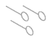
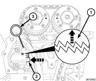
Reset the LH cam chain tensioner by lifting the pawl (1), pushing back the piston (2) and installing Tensioner Pin 8514 (3) (Refer to 09 - Engine/Valve Timing - Standard Procedure)
.
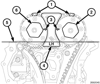
NOTE: Minor rotation of a camshaft (a few degrees) may be required to install the camshaft phaser lock.
- Install the LH Camshaft Phaser Lock 10202 (4).
- Loosen both the intake oil control valve (6) and exhaust oil control valve (2).
- Remove the LH Camshaft Phaser Lock 10202 (4).
- Remove the oil control valve (2) from the left side exhaust cam phaser and pull the phaser off of the camshaft.
-
Remove the oil control valve (6) from the left side intake cam phaser and pull the phaser off of the camshaft.
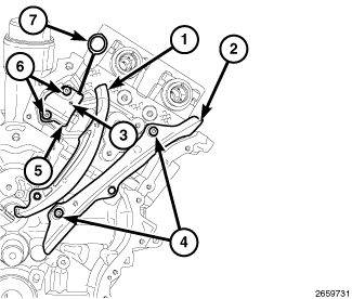
- Remove the LH cam chain tensioner arm (1).
- Remove two T30 bolts (6) and the LH cam chain tensioner (5).
-
Remove two T30 bolts (4) and the LH cam chain guide (2).
-
Remove the left camshafts (Refer to 09 - Engine/Cylinder Head/CAMSHAFT, Engine - Removal)
NOTE: If the rocker arms are to be reused, identify their positions so that they can be reassembled into their original locations.
-
Remove the rocker arms (Refer to 09 - Engine/Cylinder Head/ROCKER ARM, Valve - Removal)
NOTE: If the hydraulic lifters are to be reused, identify their positions so that they can be reassembled into their original locations.
- If required, remove the hydraulic lifters (Refer to 09 - Engine/Cylinder Head/LIFTER(S) , Hydraulic - Removal)
-
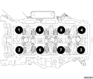
Using the sequence shown, remove the cylinder head retaining bolts.
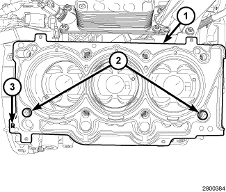
NOTE: Right head gasket shown, left head gasket similar.
WARNING: The multi-layered steel head gaskets have very sharp edges that could cause personal injury if not handled carefully.
NOTE: The head gasket (1) crimps the locating dowels (2) and the dowels may pull out of the engine block when the head gasket is removed.
-
Remove the cylinder head and gasket (1). Discard the gasket.
CAUTION: Do not lay the cylinder head on its gasket sealing surface, due to the design of the cylinder head gasket, any distortion to the cylinder head sealing surface may prevent the gasket from properly sealing resulting in leaks.
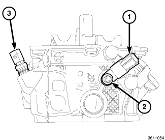
- If required, remove the Engine Coolant Temperature (ECT) sensor (3).
-
If required, remove the bolt (2) and the ignition coil capacitor (1).
RIGHT
|
The magnetic timing wheels (1)
must not come in contact with magnets (pickup tools, trays, etc.)
or any other strong magnetic field. This will destroy the timing wheels
ability to correctly relay camshaft position to the camshaft position
sensor.
CAUTION:
|
- Perform the fuel pressure release procedure (Refer to 14 - Fuel System/Fuel Delivery - Standard Procedure) .
- Disconnect and isolate the negative battery cable.
-
Remove the engine cover (1).
-
Remove the air cleaner body (1) (Refer to 09 - Engine/Air Intake System/BODY, Air Cleaner - Removal)
.
-
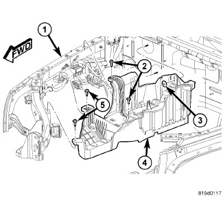
Remove the battery, Totally Integrated Power Module (TIPM) and battery tray (4) (Refer to 08 - Electrical/8F - Engine Systems/Battery System/TRAY, Battery - Removal)
.
- Raise and support the vehicle (Refer to 04 - Vehicle Quick Reference/Hoisting - Standard Procedure) .
- Drain the cooling system (Refer to 07 - Cooling - Standard Procedure) .
- Drain the engine oil (Refer to 09 - Engine/Lubrication/OIL - Standard Procedure) .
- Disconnect the left upstream (3) and downstream (1) oxygen sensor connectors from the main wire harness.
-
Remove the right catalytic converter (Refer to 11 - Exhaust System/CONVERTER, Catalytic - Removal)
.
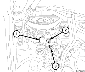
- Disengage the wiring harness routing retainer (3) from the power steering pump bracket (1).
-
Remove the lower power steering pump retaining bolt (2).
- Lower the vehicle.
-
Remove the upper and lower intake manifolds (2) and insulator (Refer to 09 - Engine/Manifolds/MANIFOLD, Intake - Removal)
- Remove the right and left cylinder head covers (Refer to 09 - Engine/Cylinder Head/COVER(S) , Cylinder Head - Removal).
-
Remove the accessory drive belt (7) (Refer to 07 - Cooling/Accessory Drive/BELT, Serpentine - Removal)
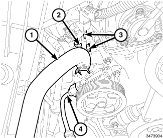
- Disengage the wiring harness routing retainer (2) from the power steering pump bracket.
-
Remove the upper power steering pump bracket retaining bolts (3) and reposition the pump (with bracket).
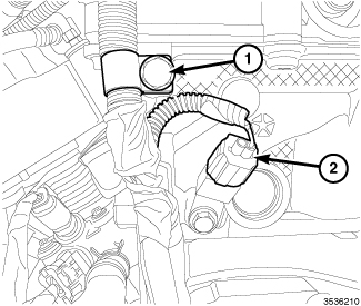
- Disconnect the electrical connector (2) from the ignition coil capacitor.
-
Remove the bolt (1) and the main wire harness retainer from the rear of the right cylinder head.
- Remove the spark plugs (Refer to 08 - Electrical/8I - Ignition Control/SPARK PLUG - Removal) .
-
Remove the oil pan, crankshaft vibration damper and engine timing cover (Refer to 09 - Engine/Valve Timing/COVER(S)
, Engine Timing - Removal)
NOTE: Take this opportunity to measure timing chain wear (Refer to 09 - Engine/Valve Timing - Standard Procedure) .
-
Lower the vehicle.
CAUTION: When aligning timing marks, always rotate engine by turning the crankshaft. Failure to do so will result in valve and/or piston damage.
-
Rotate the crankshaft CW to place the number one piston at TDC on the exhaust stroke by aligning the dimple (4) on the crankshaft with the block/bearing cap junction (5). The left side cam phaser arrows (2) should point toward each other and be parallel to the valve cover sealing surface (3). The right side cam phaser arrows (7) should point away from each other and the scribe lines (9) should be parallel to the valve cover sealing surface (8).
CAUTION: Always reinstall timing chains so that they maintain the same direction of rotation. Inverting a previously run chain on a previously run sprocket will result in excessive wear to both the chain and sprocket.
-
Mark the direction of rotation on the timing chain using a paint pen or equivalent to aid in reassembly.
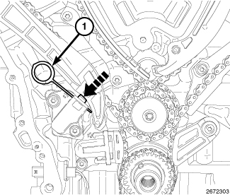
CAUTION: When the timing chains are removed and the cylinder heads are still installed, DO NOT rotate the camshafts or crankshaft without first locating the proper crankshaft position. Failure to do so will result in valve and/or piston damage.
-
Reset the RH cam chain tensioner by pushing back the tensioner piston and installing Tensioner Pin 8514 (1).
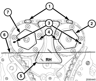
NOTE: Minor rotation of a camshaft (a few degrees) may be required to install the camshaft phaser lock.
- Install the RH Camshaft Phaser Lock 10202 (5).
- Loosen both the intake oil control valve (2) and exhaust oil control valve (7).
- Remove the RH Camshaft Phaser Lock 10202 (5).
- Remove the oil control valve (2) from the right side intake cam phaser and pull the phaser off of the camshaft.
-
Remove the oil control valve (7) from the right side exhaust cam phaser and pull the phaser off of the camshaft.
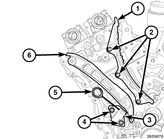
- Remove the RH cam chain tensioner arm (6).
- Remove two T30 bolts (4) and the RH cam chain tensioner (3).
-
Remove three T30 bolts (2) and the RH cam chain guide (1).
-
Remove the right camshafts (Refer to 09 - Engine/Cylinder Head/CAMSHAFT, Engine - Removal)
NOTE: If the rocker arms are to be reused, identify their positions so that they can be reassembled into their original locations.
-
Remove the rocker arms (Refer to 09 - Engine/Cylinder Head/ROCKER ARM, Valve - Removal)
NOTE: If the hydraulic lifters are to be reused, identify their positions so that they can be reassembled into their original locations.
- If required, remove the hydraulic lifters (Refer to 09 - Engine/Cylinder Head/LIFTER(S) , Hydraulic - Removal)
-
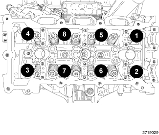
Using the sequence shown, remove the cylinder head retaining bolts.
WARNING: The multi-layered steel head gaskets have very sharp edges that could cause personal injury if not handled carefully.
NOTE: The head gasket (1) crimps the locating dowels (2) and the dowels may pull out of the engine block when the head gasket is removed.
-
Remove the cylinder head and gasket. Discard the gasket.
CAUTION: Do not lay the cylinder head on its gasket sealing surface, due to the design of the cylinder head gasket, any distortion to the cylinder head sealing surface may prevent the gasket from properly sealing resulting in leaks.
-
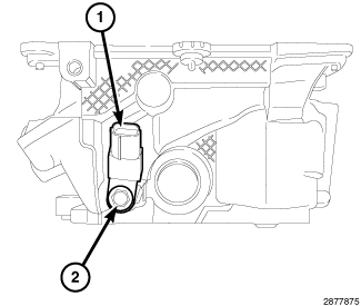
If required, remove the bolt (2) and the ignition coil capacitor (1).
CLEANING
When cleaning cylinder head and
cylinder block surfaces, DO NOT use a metal scraper because the surfaces
could be cut or ground. Use ONLY a wooden or plastic scraper.
CAUTION:
To ensure engine gasket sealing, proper surface preparation must be performed, especially with the use of aluminum engine components and multi-layer steel cylinder head gaskets.
| NOTE: |
Multi-Layer Steel (MLS) head gaskets require a scratch free sealing surface. |
- Remove all gasket material from cylinder head and block (Refer to 09 - Engine - Standard Procedure) . Be careful not to gouge or scratch the aluminum head sealing surface.
-
Clean all engine oil
passages.
CAUTION: Non-compressible debris such as oil, coolant or RTV sealants that are not removed from bolt holes can cause the aluminum casting to crack when tightening the bolts.
- Clean out the cylinder head bolt holes in the engine block. DO NOT USE any adhesives when installing the MLS head gaskets. The use of adhesives may cause the gasket not to seal properly and may leak. MLS gaskets are to be installed on a surface free of debris and oils.
INSPECTION
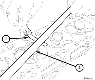 |
- Check cylinder head warpage with a straight edge (2) and feeler gauge (1).
- Cylinder head must be flat within specification (Refer to 09 - Engine - Specifications) .
- Verify that the valve tappets move freely in theirs bores and that they have been rotating.
- Inspect camshaft bearing journals for scoring.
- Remove carbon and varnish deposits from inside of valve guides with a reliable guide cleaner.
- Inspect the following components and verify that they are within specification (Refer to 09 - Engine - Specifications) :
LEFT
|
The magnetic timing wheels (1)
must not come in contact with magnets (pickup tools, trays, etc.)
or any other strong magnetic field. This will destroy the timing wheels
ability to correctly relay camshaft position to the camshaft position
sensor.
CAUTION:
|
- If removed, install the Engine Coolant Temperature (ECT) sensor (4) and tighten to 11 N·m (97 in. lbs.).
-
If removed, install
the ignition coil capacitor (1) with a M6 bolt (2) tightened to 10
N·m (89 in. lbs.).
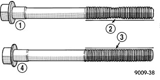
CAUTION: The cylinder head bolts are tightened using a torque plus angle procedure. The bolts must be examined BEFORE reuse. If the threads are necked down the bolts must be replaced.
NOTE: Typical cylinder head bolt shown.
-
Check cylinder head
bolts for necking by holding a scale or straight edge against the
threads. If all the threads do not contact the scale (2) the bolt
must be replaced.
NOTE: Right head gasket shown, left head gasket similar.
CAUTION: When cleaning cylinder head and cylinder block surfaces, DO NOT use a metal scraper because the surfaces could be cut or ground. Use ONLY a wooden or plastic scraper.
-
Clean and prepare the
gasket sealing surfaces of the cylinder head and block (Refer to 09 - Engine - Standard Procedure)
.
CAUTION: Non-compressible debris such as oil, coolant or RTV sealants that are not removed from bolt holes can cause the aluminum casting to crack when tightening the bolts.
-
Clean out the cylinder
head bolt holes in the engine block.
WARNING: The multi-layered steel head gaskets have very sharp edges that could cause personal injury if not handled carefully.
CAUTION: The installation of the cylinder head gaskets are not interchangeable between the left and right cylinder heads. They are clearly marked (3) with "R" for right and "L" for left. They must be applied on a dry surface, without the use of any adhesives.
-
Position the new cylinder
head gasket (1) on the locating dowels (2).
-
Position the cylinder
head onto the cylinder block. Make sure the cylinder head seats fully
over the locating dowels.
NOTE: Do not apply any additional oil to the bolt threads.
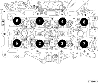
- Install the eight head bolts finger tight.
-
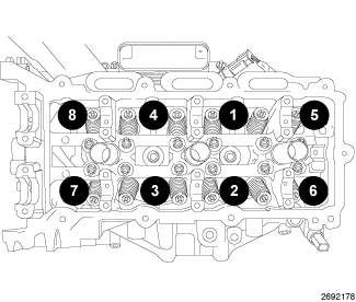
Tighten the cylinder
head bolts in the sequence shown, following this 9 step torque plus
angle method. Tighten according to the following torque values:
- Step 1: All to 30 N·m (22 ft. lbs.)
- Step 2: All to 45 N·m (33 ft. lbs.)
- Step 3: All + 75° Turn Do not use a torque wrench for this step.
- Step 4: All + 50° Turn Do not use a torque wrench for this step.
- Step 5: Loosen all fasteners in reverse of sequence shown
- Step 6: All to 30 N·m (22 ft. lbs.)
- Step 7: All to 45 N·m (33 ft. lbs.)
- Step 8: All + 70° Turn Do not use a torque wrench for this step.
-
Step 9: All + 70° Turn Do not use a torque
wrench for this step.
NOTE: If the hydraulic lifters are being reused, reassemble them into their original locations.
-
If removed, install
the hydraulic lifters (Refer
to 09 - Engine/Cylinder Head/LIFTER(S)
, Hydraulic - Installation)
NOTE: If the rocker arms are being reused, reassemble them into their original locations.
CAUTION: Do not rotate the camshafts more than a few degrees independently of the crankshaft. Valve to piston contact could occur resulting in possible valve damage. If the camshafts need to be rotated more than a few degrees, first move the pistons away from the cylinder heads by rotating the crankshaft counterclockwise to a position 30° before-top-dead-center. Once the camshafts are returned to their top-dead-center position, rotate the crankshaft clockwise to return the crankshaft to top-dead-center.
- Install the rocker arms and camshafts (Refer to 09 - Engine/Cylinder Head/CAMSHAFT, Engine - Installation)
-
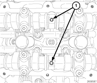
Rotate the camshafts
CW to TDC by positioning the alignment holes (1) vertically.
- Install the LH cam chain guide (2) with two bolts (4). Tighten the T30 bolts (4) to 12 N·m (106 in. lbs.).
- Install the LH cam chain tensioner (5) to the cylinder head with two bolts (6). Tighten the T30 bolts (6) to 12 N·m (106 in. lbs.).
- Reset the LH cam chain tensioner (5) by lifting the pawl (3), pushing back the piston and installing Tensioner Pin 8514 (7) (Refer to 09 - Engine/Valve Timing - Standard Procedure) .
-
Install the LH tensioner
arm (1).
-
Press the LH intake
cam phaser onto the intake camshaft. Install and hand tighten the
oil control valve.
CAUTION: Always reinstall timing chains so that they maintain the same direction of rotation. Inverting a previously run chain on a previously run sprocket will result in excessive wear to both the chain and sprocket.
-
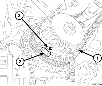
Drape the left side
cam chain over the LH intake cam phaser and onto the idler sprocket
(1) so that the arrow (3) is aligned with the plated link (2) on the
cam chain.
-
While maintaining this
alignment, route the cam chain around the exhaust and intake cam phasers
so that the plated links are aligned with the phaser timing marks
(1). Position the left side cam phasers so that the arrows (3) point
toward each other and are parallel to the valve cover sealing surface
(5). Press the exhaust cam phaser onto the exhaust cam, install and
hand tighten the oil control valve (2).
NOTE: Minor rotation of a camshaft (a few degrees) may be required to install the camshaft phaser or phaser lock.
-
Install the LH Camshaft
Phaser Lock 10202 (4) and tighten the oil control valves (2) and (6) to 150
N·m (110 ft. lbs.).
- Remove the LH Camshaft Phaser Lock 10202 .
- Remove the Tensioner Pin 8514 (1) from the LH cam chain tensioner.
- Rotate the crankshaft CW two complete revolutions stopping when the dimple (4) on the crankshaft is aligned the with the block/bearing cap junction (5).
-
While maintaining this
alignment, verify that the arrows on the left side cam phasers (2)
point toward each other and are parallel to the valve cover sealing
surface (3) and that the right side cam phaser arrows (7) point away
from each other and the scribe lines (9) are parallel to the valve
cover sealing surface (8).
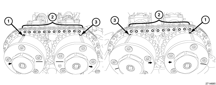
- There should be 12 chain pins (2) between the exhaust cam phaser triangle marking (1) and the intake cam phaser circle marking (3).
- If the engine timing is not correct, repeat this procedure.
-
Install the engine
timing cover, crankshaft vibration damper, upper and lower oil pans (Refer to 09 - Engine/Valve Timing/COVER(S)
,
Engine Timing - Installation)
-
Connect the ignition
coil capacitor electrical connector (1).
-
Install the A/C compressor
(2) onto the engine with four bolts (1) tightened to 28 N·m (21 ft.
lbs.).
- Install the accessory drive belt (7) (Refer to 07 - Cooling/Accessory Drive/BELT, Serpentine - Installation) .
-
Install the right and
left cylinder head covers (Refer
to 09 - Engine/Cylinder Head/COVER(S)
, Cylinder Head - Installation).
NOTE: Right catalytic converter shown, left catalytic converter similar.
- Install the left catalytic converter (Refer to 11 - Exhaust System/CONVERTER, Catalytic - Installation) .
-
Connect the upstream
(3) and downstream (1) oxygen sensor connectors to the main wire harness.
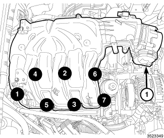
- Install the upper and lower intake manifolds (Refer to 09 - Engine/Manifolds/MANIFOLD, Intake - Installation)
-
Install the front wheelhouse
inner splash shields (Refer
to 23 - Body/Exterior/SHIELD, Splash - Installation)
.
-
Install the air inlet
hose (3) and the air cleaner body (Refer to 09 - Engine/Air Intake System/BODY, Air Cleaner - Installation)
- If removed, install the oil filter and fill the engine crankcase with the proper oil to the correct level (Refer to 09 - Engine/Lubrication/OIL - Standard Procedure)
- Fill the cooling system (Refer to 07 - Cooling - Standard Procedure) .
- Install the engine cover (1).
- Connect the negative battery cable and tighten nut to 5 N·m (45 in. lbs.).
- Run the engine until it reaches normal operating temperature. Check cooling system for correct fluid level (Refer to 07 - Cooling - Standard Procedure)
| NOTE: |
The Cam/Crank Variation
Relearn procedure must be performed using the scan tool anytime there
has been a repair/replacement made to a powertrain system, for example:
flywheel, valvetrain, camshaft and/or crankshaft sensors or components. |
RIGHT
|
The magnetic timing wheels (1)
must not come in contact with magnets (pickup tools, trays, etc.)
or any other strong magnetic field. This will destroy the timing wheels
ability to correctly relay camshaft position to the camshaft position
sensor.
CAUTION:
|
-
If removed, install
the ignition coil capacitor (1) with a M6 bolt (2) tightened to 10
N·m (89 in. lbs.).
CAUTION: The cylinder head bolts are tightened using a torque plus angle procedure. The bolts must be examined BEFORE reuse. If the threads are necked down the bolts must be replaced.
NOTE: Typical cylinder head bolt shown.
-
Check cylinder head
bolts for necking by holding a scale or straight edge against the
threads. If all the threads do not contact the scale (2) the bolt
must be replaced.
CAUTION: When cleaning cylinder head and cylinder block surfaces, DO NOT use a metal scraper because the surfaces could be cut or ground. Use ONLY a wooden or plastic scraper.
-
Clean and prepare the
gasket sealing surfaces of the cylinder head and block (Refer to 09 - Engine - Standard Procedure)
.
CAUTION: Non-compressible debris such as oil, coolant or RTV sealants that are not removed from bolt holes can cause the aluminum casting to crack when tightening the bolts.
-
Clean out the cylinder
head bolt holes in the engine block.
WARNING: The multi-layered steel head gaskets have very sharp edges that could cause personal injury if not handled carefully.
CAUTION: The installation of the cylinder head gaskets are not interchangeable between the left and right cylinder heads. They are clearly marked (3) with "R" for right and "L" for left. They must be applied on a dry surface, without the use of any adhesives.
-
Position the new cylinder
head gasket (1) on the locating dowels (2).
-
Position the cylinder
head onto the cylinder block. Make sure the cylinder head seats fully
over the locating dowels.
NOTE: Do not apply any additional oil to the bolt threads.
- Install the eight head bolts finger tight.
-
Tighten the cylinder
head bolts in the sequence shown, following this 9 step torque plus
angle method. Tighten according to the following torque values:
- Step 1: All to 30 N·m (22 ft. lbs.)
- Step 2: All to 45 N·m (33 ft. lbs.)
- Step 3: All + 75° Turn Do not use a torque wrench for this step.
- Step 4: All + 50° Turn Do not use a torque wrench for this step.
- Step 5: Loosen all fasteners in reverse of sequence shown
- Step 6: All to 30 N·m (22 ft. lbs.)
- Step 7: All to 45 N·m (33 ft. lbs.)
- Step 8: All + 70° Turn Do not use a torque wrench for this step.
-
Step 9: All + 70° Turn Do not use a torque
wrench for this step.
NOTE: If the hydraulic lifters are being reused, reassemble them into their original locations.
-
If removed, install
the hydraulic lifters (Refer
to 09 - Engine/Cylinder Head/LIFTER(S)
, Hydraulic - Installation)
NOTE: If the rocker arms are being reused, reassemble them into their original locations.
-
Install the rocker
arms and camshafts (Refer to
09 - Engine/Cylinder Head/CAMSHAFT, Engine - Installation)
CAUTION: Do not rotate the camshafts more than a few degrees independently of the crankshaft. Valve to piston contact could occur resulting in possible valve damage. If the camshafts need to be rotated more than a few degrees, first move the pistons away from the cylinder heads by rotating the crankshaft counterclockwise to a position 30° before-top-dead-center. Once the camshafts are returned to their top-dead-center position, rotate the crankshaft clockwise to return the crankshaft to top-dead-center.
-
Verify that the camshafts
are set at TDC by positioning the alignment holes (1) vertically.
- Install the RH cam chain guide (1) with three bolts (2). Tighten the T30 bolts (2) to 12 N·m (106 in. lbs.).
- Install the RH cam chain tensioner (3) to the engine block with two bolts (4). Tighten the T30 bolts (4) to 12 N·m (106 in. lbs.).
- Reset the RH cam chain tensioner (3) by pushing back the tensioner piston and installing Tensioner Pin 8514 (5).
-
Install the RH tensioner
arm (6).
-
Press the RH exhaust
cam phaser onto the exhaust camshaft. Install and hand tighten the
oil control valve.
CAUTION: Always reinstall timing chains so that they maintain the same direction of rotation. Inverting a previously run chain on a previously run sprocket will result in excessive wear to both the chain and sprocket.
-
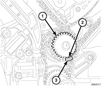
Drape the right side
cam chain over the RH exhaust cam phaser and onto the idler sprocket
(1) so that the dimple (2) is aligned with the plated link (3) on
the cam chain.
-
While maintaining this
alignment, route the cam chain around the exhaust and intake cam phasers
so that the plated links are aligned with the phaser timing marks
(1). Position the right side cam phasers so that the arrows (3) point
away from each other and the scribe lines (4) are parallel to the
valve cover sealing surface (6). Press the intake cam phaser onto
the intake cam, install and hand tighten the oil control valve (2).
NOTE: Minor rotation of a camshaft (a few degrees) may be required to install the camshaft phaser or phaser lock.
-
Install the RH Camshaft
Phaser Lock 10202 (5) and tighten the oil control valves (2) and (7) to 150
N·m (110 ft. lbs.).
- Remove the RH Camshaft Phaser Lock 10202 .
- Remove the Tensioner Pin 8514 (6) from the RH cam chain tensioner.
- Rotate the crankshaft CW two complete revolutions stopping when the dimple (4) on the crankshaft is aligned the with the block/bearing cap junction (5).
-
While maintaining this
alignment, verify that the arrows on the left side cam phasers (2)
point toward each other and are parallel to the valve cover sealing
surface (3) and that the right side cam phaser arrows (7) point away
from each other and the scribe lines (9) are parallel to the valve
cover sealing surface (8).
- There should be 12 chain pins (2) between the exhaust cam phaser triangle marking (1) and the intake cam phaser circle marking (3).
- If the engine timing is not correct, repeat this procedure.
-
Install the engine
timing cover, crankshaft vibration damper, upper and lower oil pans (Refer to 09 - Engine/Valve Timing/COVER(S)
,
Engine Timing - Installation)
- Secure the main wire harness retainer to the rear of the right cylinder head with the bolt (1) tightened to 12 N·m (106 in. lbs.).
-
Connect the electrical
connector (2) to the ignition coil capacitor.
- Position the power steering pump (with bracket) and install the upper power steering pump bracket retaining bolts (3). Do not tighten at this time.
-
Engage the wiring harness
routing retainer (2) to the power steering pump bracket.
- Raise and support the vehicle (Refer to 04 - Vehicle Quick Reference/Hoisting - Standard Procedure) .
- Engage the wiring harness routing retainer (3) to the power steering pump bracket (1).
-
Install the lower power
steering pump retaining bolt (2) and tighten all three retaining
bolts to 24 N·m (18 ft. lbs.).
- Install the accessory drive belt (7) (Refer to 07 - Cooling/Accessory Drive/BELT, Serpentine - Installation) .
-
Install the right and
left cylinder head covers (Refer
to 09 - Engine/Cylinder Head/COVER(S)
, Cylinder Head - Installation).
- Install the right catalytic converter (Refer to 11 - Exhaust System/CONVERTER, Catalytic - Installation) .
-
Connect the upstream
(3) and downstream (1) oxygen sensor connectors to the main wire harness.
-
Install the upper and
lower intake manifolds (Refer
to 09 - Engine/Manifolds/MANIFOLD, Intake - Installation)
- Install the battery tray (4), Totally Integrated Power Module (TIPM) and battery (Refer to 08 - Electrical/8F - Engine Systems/Battery System/TRAY, Battery - Installation) .
-
Install the front wheelhouse
inner splash shields (Refer
to 23 - Body/Exterior/SHIELD, Splash - Installation)
.
-
Install the air inlet
hose (3) and the air cleaner body (Refer to 09 - Engine/Air Intake System/BODY, Air Cleaner - Installation)
- If removed, install the oil filter and fill the engine crankcase with the proper oil to the correct level (Refer to 09 - Engine/Lubrication/OIL - Standard Procedure)
- Fill the cooling system (Refer to 07 - Cooling - Standard Procedure) .
- Install the engine cover (1).
- Connect the negative battery cable and tighten nut to 5 N·m (45 in. lbs.).
- Run the engine until it reaches normal operating temperature. Check cooling system for correct fluid level (Refer to 07 - Cooling - Standard Procedure)
| NOTE: |
The Cam/Crank Variation
Relearn procedure must be performed using the scan tool anytime there
has been a repair/replacement made to a powertrain system, for example:
flywheel, valvetrain, camshaft and/or crankshaft sensors or components. |