Column
DESCRIPTION
| NOTE: |
The steering column on vehicles with an automatic transmission may not be equipped with an internal locking shaft that allows the ignition key cylinder to be locked with the key. Alternative methods of locking the steering wheel for service will have to be used. |
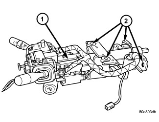
The standard tilt steering column has been designed to be serviced as an assembly. The column is connected to the steering gear with an upper and lower intermediate shaft. The upper shaft has a support bearing mounted to a bracket. The bracket mounts to the dash panel wall with two nuts. These shafts and bearing are serviceable. The key cylinder, switches, clock spring, trim shrouds and steering wheel are serviced separately.
OPERATION
Safety goggles should be worn at all times when working on steering columns.
To service the steering wheel, switches or airbag, refer to Electrical - Restraints and follow all WARNINGS and CAUTIONS.
The airbag system is a sensitive,
complex electro-mechanical unit. Before attempting to diagnose, remove
or install the airbag system components you must first disconnect
and isolate the battery negative (ground) cable. Then wait two minutes
for the system capacitor to discharge. Failure to do so could result
in accidental deployment of the airbag and possible personal injury.
The fasteners, screws, and bolts, originally used for the airbag components,
have special coatings and are specifically designed for the airbag
system. They must never be replaced with any substitutes. Anytime
a new fastener is needed, replace with the correct fasteners provided
in the service package or fasteners listed in the parts books.
WARNING:
DIAGNOSIS AND TESTING - STEERING COLUMN
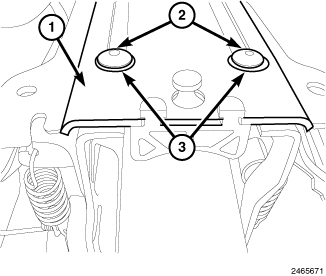
The two steering column bracket halves are riveted together above the steering column with raised locator pads under the rivets (when viewed from the top). These rivets and locator pads can help determine if column has been compromised. If the steering column has collapsed, the rivets will slide down the slotted upper half of the bracket with the steering column. A collapse may occur with the tube housing moving into the rear bracket assembly OR the tube may move inside the tube housing. Typically if a collapse happens, the rivets/locator pads should indicate damage. However, if any of the following steps indicate a collapse, the steering column will still need replacement.
| NOTE: |
All illustrations within this procedure are typical; however the steering column functionality is the same in all vehicles. |
 |
- Grasp the steering wheel at the 9 and 3 o'clock positions, and again at the 12 and 6 o'clock positions and attempt to rock the steering wheel back and forth and up and down. If there is excessive movement or an audible clunking or grinding sound, replace the steering column (Refer to 19 - Steering/Column - Removal) .
-
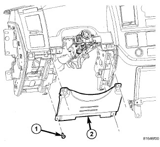
Remove the steering column opening cover, and if equipped, remove the retaining screws (1) and the steering column opening cover reinforcement (2).
-
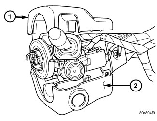
Remove screws from the lower column shroud (2) and remove both the upper and lower shrouds.
-
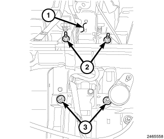
Remove the rear steering column mounting bolts (2).
NOTE: This illustration shows two vertical front steering column mounting bolts (3). Some steering column mounting brackets may have only one vertical mounting bolt in this position and another horizontal bolt. The horizontal bolt does not need to be loosened for this procedure.
-
Loosen the front steering column retaining bolts/nuts (3) several turns, but do not remove.
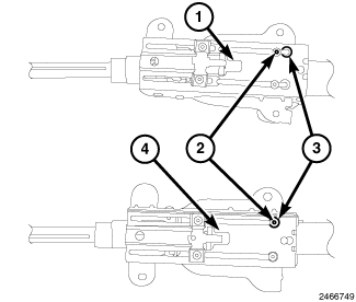
NOTE: A steering column which is in good condition (4) will have the rivets (2) centered on the raised locator pads (3). When a steering column is compromised (1), the rivets (2) should be moved off the locator pads (3).
-
Move the steering column assembly (1) down to view the rivets (2) in the top of the bracket (between instrument cluster and steering column). Verify that the rivets (2) have not moved off center of the locator pads (3). If the rivets (2) have moved, replace the steering column (Refer to 19 - Steering/Column - Removal)
.
- Remove the clockspring (Refer to 10 - Restraints/CLOCKSPRING - Removal) .
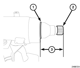
- Measure the distance from the edge of the steering column housing tube (1) to the edge of the splined shaft (2). If the measurement (3) is less than 40 mm (1.574 in.), replace the steering column (Refer to 19 - Steering/Column - Removal) .
- If the steering column passes all tests and measurements above, the steering column is not collapsed and should not need to be replaced.
SPECIFICATIONS
| DESCRIPTION | N·m |
Ft. Lbs. |
In. Lbs. |
|---|---|---|---|
|
Steering Wheel Nut |
43 |
32 |
— |
|
Steering Column Mounting Nuts |
17 |
— |
150 |
|
Intermediate Shafts Coupler Pinch Bolts Upper AND Lower |
54 |
40 |
— |
|
Upper Intermediate Shaft Mounting Nuts |
13 |
— |
115 |
REMOVAL
- Position front wheels straight ahead.
- Remove and isolate the negative ground cable from the battery.
-
Remove the airbag, (Refer to 10 - Restraints/AIR BAG, Driver - Removal)
.
NOTE: If equipped with cruise control, disconnect clock spring harness from the cruise switch harness on the steering wheel.
-
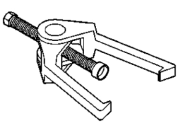
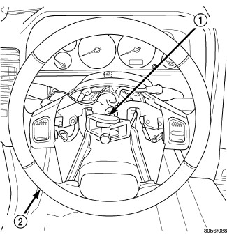
Remove the steering wheel (2) with puller C-3894-A (1) or an appropriate puller
(Refer to 19 - Steering/Column/WHEEL, Steering - Removal)
.
-
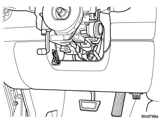
Remove steering column opening cover, (Refer to 23 - Body/Instrument Panel/COVER, Steering Column Opening - Removal)
.
-
Remove screws from the lower column shroud (2) and remove both the upper and lower shrouds.
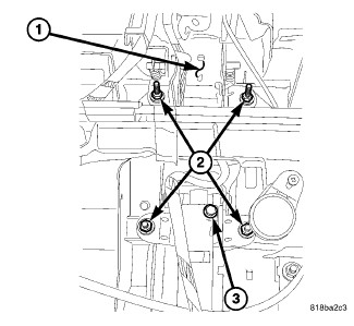
- Turn ignition key to the on position.
- If vehicle is equipped with automatic transmission, disconnect shifter interlock cable from the column.
-
Remove the steering coupler bolt and column mounting nuts (2) then lower column (1) off the mounting studs.
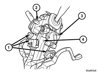
- Disconnect and remove the wiring harness (1) from the column .
-
Slide the shifter interlock cable from the tie straps.
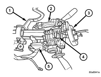
- Remove column (4).
- Transfer the necessary parts if needed.
-
Remove clock spring (3) , switches, (SKREEM if equipped) (5) (Refer to 10 - Restraints/CLOCKSPRING - Removal)
.
INSTALLATION
 |
-
Align and install column (1) into the steering coupler .
- Install column harness (1) and connect harness to switches .
-
Reroute the shifter interlock cable through the tie straps.
- Install the column (1) onto the mounting studs (2) .
-
Install the two mounting nuts and the two mounting bolts all finger tight.
CAUTION: Lower nuts must be installed and tightened first then the upper nuts in order to prevent damage to the capsules.
- Tighten the lower mounting nuts to 17 N·m (150 in. lbs.).
-
Tighten the upper mounting nuts to 17 N·m (150 in. lbs.).
- Install the steering column coupler bolt and tighten to 49 N·m (36 ft. lbs.).
- Reconnect the shifter interlock cable.
-
Center the clock spring (3) (if necessary) and install it on the column (4) , (Refer to 10 - Restraints/CLOCKSPRING - Installation)
.
-
Snap together the column shrouds (1AND2) and install the mounting screws .
-
Install the steering column opening cover (Refer to 23 - Body/Instrument Panel/COVER, Steering Column Opening - Installation)
.
NOTE: Do not reuse the old steering wheel bolt (a new bolt must be used)
NOTE: Be certain that the steering wheel mounting bolt is tightened to the proper torque specification to ensure proper clockspring operation.
-
Install the steering wheel and tighten bolt to 54 N·m (40 ft. lbs.) (Refer to 19 - Steering/Column/WHEEL, Steering - Installation)
.
NOTE: If equipped with cruise control, connect clock spring harness to cruise switch harness on the steering wheel.
- Install the airbag, (Refer to 10 - Restraints/AIR BAG, Driver - Installation) .
- Install the negative battery terminal.