Manual, NSG370
- DIAGNOSIS AND TESTING - MANUAL TRANSMISSION - NSG370
- STANDARD PROCEDURE - DRAIN AND FILL
- SPECIFICATIONS
- REMOVAL
- DISASSEMBLY
- CLEANING
- INSPECTION
- ASSEMBLY
- INSTALLATION
- SPECIAL TOOLS
DIAGNOSIS AND TESTING - MANUAL TRANSMISSION - NSG370
LOW LUBRICANT LEVEL
A low transmission lubricant level is generally the result of a leak, inadequate lubricant fill or incorrect lubricant level check.
Rear transmission leaks will be from the oil seals or component mating surfaces.
Front transmission leaks will be from the front input shaft retainer seal. Lubricant may drip from the clutch housing after extended operation. If leak is severe, it may contaminate the clutch disc.
Lubricant level check can only be made when the vehicle is level and allowing the lubricant to settle for a minute before checking. This will ensure an accurate check and avoid an under filled or over filled condition.
HARD SHIFTING
Hard shifting is usually caused by low lubricant level, improper or contaminated lubricants. This will cause noise, excessive wear, internal bind, and hard shifting. Substantial lubricant leaks can result in gear, shift rail, synchro, and bearing damage. The first indications of component damage is usually hard shifting and noise.
Shift component damage, clutch adjustment, worn pressure plate or disc are also causes of increased shift effort. If clutch problem is advanced, gear clash during shifts can result. Worn or damaged synchronizer rings can cause gear clash when shifting into any forward gear. In some new or rebuilt transmissions, new synchro rings may tend to stick slightly causing hard or noisy shifts. In most cases, this condition will decline as the rings wear-in.
TRANSMISSION NOISE
Most manual transmissions make some noise during normal operation. Rotating gears generate a mild whine that is audible, but generally only at extreme speeds.
Severe, highly audible transmission noise is generally the initial indicator of a lubricant problem. Insufficient, improper or contaminated lubricant will promote rapid wear of gears, synchronizers, shift rails, forks and bearings. The overheating caused by a lubricant problem, can also lead to gear and bearing damage.
STANDARD PROCEDURE - DRAIN AND FILL
 |
- With vehicle in neutral, position vehicle on hoist.
- Loosen the exhaust as necessary to gain access to drain plug. (Refer to 11 - Exhaust System/CONVERTER, Catalytic - Removal) .
-
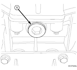
Remove drain plug (1) and drain fluid.
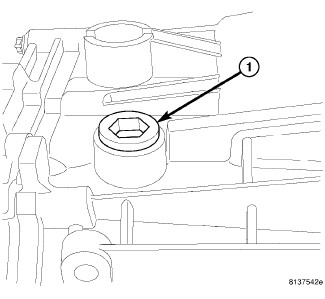
- Install drain plug and remove fill plug (1).
- Fill transmission with 1.5 L (3.17 pts.) of Mopar® Manual Transmission Lubricant MS-9224 or to the bottom of the fill plug (1) hole.
-
Install the exhaust. (Refer to 11 - Exhaust System/CONVERTER, Catalytic - Installation)
.
SPECIFICATIONS
| DESCRIPTION | N·m |
Ft. Lbs. |
In. Lbs. |
|---|---|---|---|
|
Drain Plug |
30 |
22 |
- |
|
Fill Plug |
30 |
22 |
- |
|
Shift Tower Bolts |
14 |
10 |
- |
|
Shift Lever Bolt |
4 |
- |
33 |
|
Housing Bolts |
28 |
20 |
- |
|
Input Shaft Retainer Bolts |
9 |
- |
80 |
|
Bearing Retainer Bolts |
10 |
- |
88 |
|
Shift Rail Support Bolts |
8 |
- |
71 |
|
Idler Gear Shaft Bolt |
20 |
15 |
- |
|
Countershaft Bolt |
100 |
74 |
- |
|
Transmission - Top Four Bolts |
40 |
30 |
- |
|
Transmission - Side Two Bolts |
68 |
50 |
- |
|
Transmission - Bottom Four Bolts |
54 |
40 |
- |
|
Crossmember Bolts |
47 |
35 |
- |
|
Transmission Mount Bolts |
47 |
35 |
- |
GEAR RATIOS
|
GEAR |
RATIO |
|---|---|
|
FIRST |
4.46 |
|
SECOND |
2.61 |
|
THIRD |
1.72 |
|
FOURTH |
1.24 |
|
FIFTH |
1.00 |
|
SIXTH |
0.84 |
|
REVERSE |
4.06 |
REMOVAL
 |
- Disconnect negative battery cable.
- With vehicle in neutral, position vehicle on hoist.
-
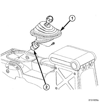
Slide shift lever boot (1) up and remove shift lever bolt and lever (2) (Refer to 21 - Transmission and Transfer Case/Manual/LEVER, Shift - Removal)
.
- Raise vehicle.
- Remove skid plates.
-
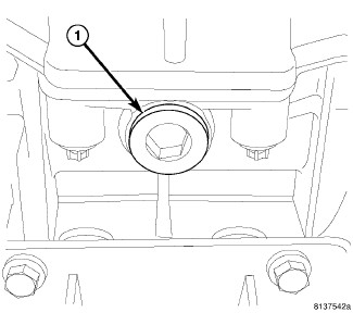
Remove drain plug (1) and drain fluid.
-
Remove catalyst assembly (Refer to 11 - Exhaust System/CONVERTER, Catalytic - Removal)
.
-
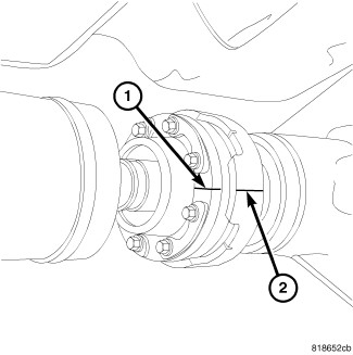
Mark transmission flange and propeller shaft for installation reference before removing propeller shaft. If 4x4 equipped mark transfer case and front propeller shaft before removing shaft (Refer to 03 - Differential and Driveline/Propeller Shaft/SHAFT, Drive - Removal)
.
-
If equipped, remove transfer case shift linkages, wiring connectors (2), and vent hoses. Remove transfer case (Refer to 21 - Transmission and Transfer Case/Transfer Case - Removal)
.
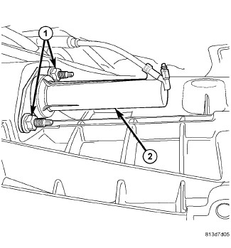
- Pull hydraulic line clip from the slave cylinder.
- Remove the line from the bracket and the cylinder.
- Remove mounting nuts (1) from slave cylinder (2).
- Remove the bracket from slave cylinder.
-
Remove the clutch slave cylinder (2) by pulling straight back.
CAUTION: Do not allow release lever plunger to pivot more than 2° in either direction in the slave cylinder bore. Allowing the plunger to pivot more than 2° in the bore will cause fluid to bypass the seal and result in fluid leakage.
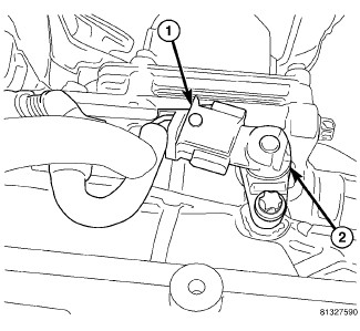
- Remove backup lamp switch (2) wiring connector (1).
-
Remove the starter. (Refer to 08 - Electrical/8F - Engine Systems/Starting/STARTER - Removal)
.
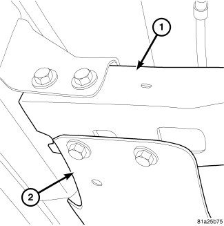
- Support transmission with jack.
- Remove crossmember (1). Lower and slide crossmember out left side of the vehicle (Refer to 13 - Frame and Bumpers/Frame/CROSSMEMBER - Removal) .
-
Remove the transmission mount.
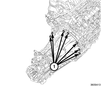
- Remove transmission bolts from engine (1).
- Move transmission rearward until input shaft is clear of clutch disc and pressure plate.
-
Lower jack and remove transmission from under vehicle.
DISASSEMBLY
 |
-
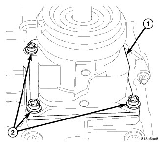
Remove shift tower (1) bolts (2) and remove tower.
-
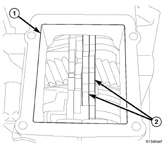
Through shift tower opening (1) shift two shift rails (2) forward to engage two gears.
-
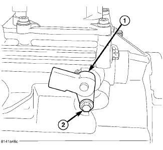
Remove back-up lamp switch (1) bolt (2) and remove switch.
-
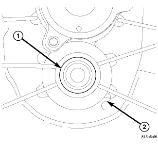
Remove countershaft plug (1) from the front housing (2) with a seal pick.
-
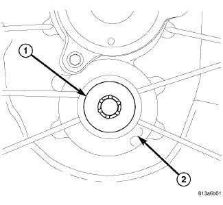
Remove countershaft bolt (1) from the front housing (2).
-
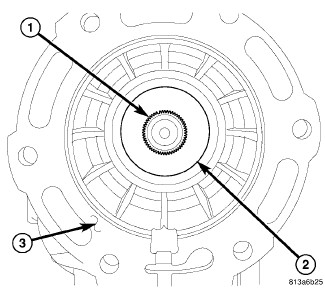
Remove output shaft (1) seal (2) from rear housing (3) with a seal pick.
-
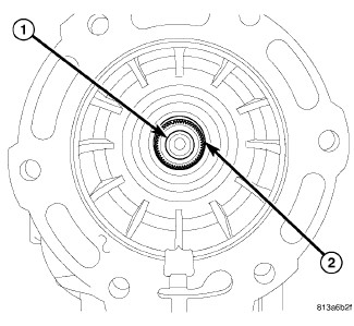
Remove output shaft (1) snap ring (2) 4x4 only.
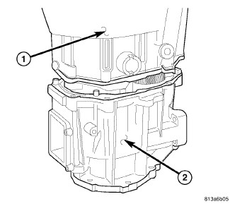
- Stand transmission on the rear housing and remove the housing bolts.
-
Remove front housing (1) from the rear housing (2).
-
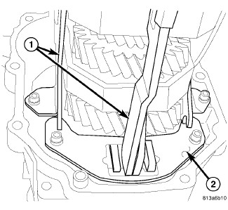
Remove shift rails (1) support plate (2) bolts.
-
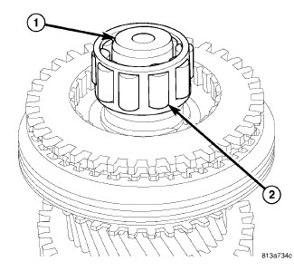
Remove input shaft (1) roller bearing (2).
-
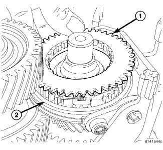
Remove fifth gear synchronizer blocker ring (1) from 5-6 synchronizer hub (2).
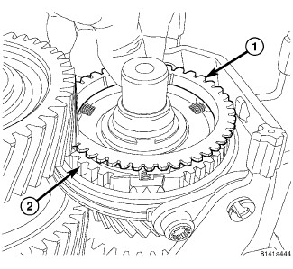
- Remove fifth gear synchronizer friction ring (1) from 5-6 synchronizer hub (2).
-
Set geartrain and shift rails with rear housing into Build Fixture 9633 .
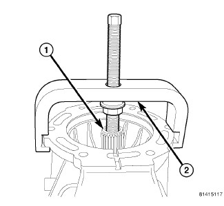
-
Remove mainshaft shaft (1) from rear housing bearing with Remover 9636 (2).
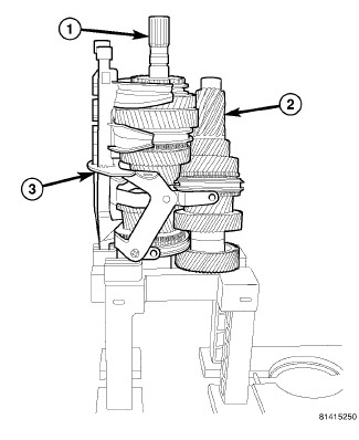
-
Remove mainshaft (1), countershaft (2) and shift rails/forks (3) from fixture.
MAINSHAFT
 |
- Place mainshaft with 5-6 synchronizer facing up in build Fixture 9648 and place in a vise.
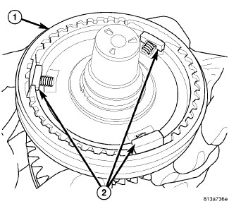
-
Push 5-6 synchronizer sleeve (1) down on hub and remove detents (2) springs and balls.
-
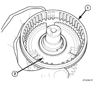
Remove 5-6 synchronizer sleeve (1) from hub (2).
-
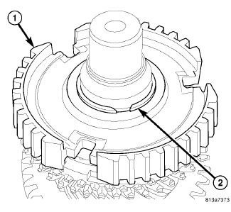
Remove 5-6 synchronizer hub (1) snap ring (2).
NOTE: All snap rings are select fit from the factory, and must be installed in their original location.
-
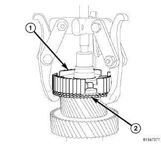
Remove 5-6 synchronizer hub (1) and sixth gear synchronizer rings (2) with a three jaw puller. Place puller jaws under sixth gear synchronizer rings (2).
-
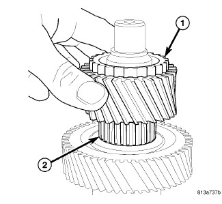
Remove sixth gear (1) and bearing (2).
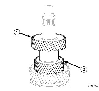
- Third gear (1) and fourth gear (2) are serviced with the mainshaft only.
-
Remove mainshaft from Fixture 9648 . Turn fixture over in vise and set opposite end of mainshaft in the fixture.
-
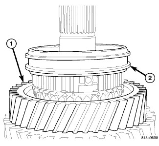
Remove reverse gear (1) synchronizer sleeve (2) off synchronizer hub.
-
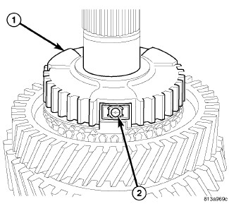
Remove reverse synchronizer hub (1) detents (2).
-
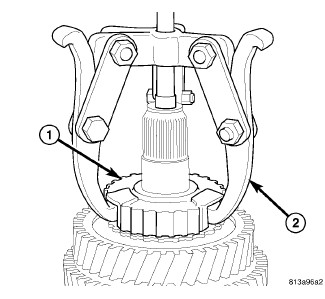
Remove reverse synchronizer hub (1) with three jaw puller (2). Place puller jaws in hub detent openings.
-
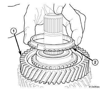
Remove reverse gear (1) synchronizer ring (2).
-
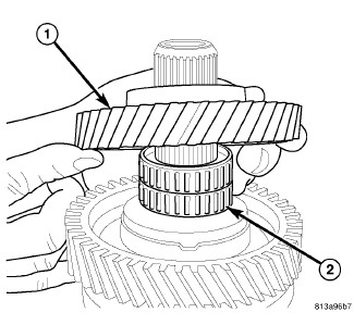
Remove reverse gear (1) and bearing (2).
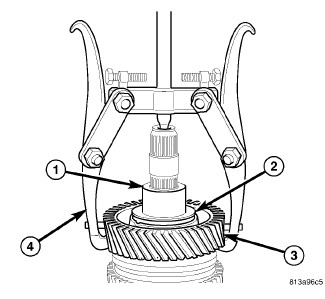
- Remove reverse gear bearing race (1), thrust washer (2) and first gear (3) with puller (4). Place puller jaws under first gear (3).
-
Remove first gear bearing.
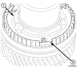
- Remove first gear synchronizer rings.
-
Push 1-2 synchronizer sleeve down on hub. Remove 1-2 synchronizer hub (1) detents (2), balls and springs.
-
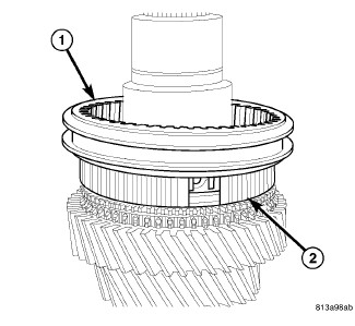
Remove 1-2 synchronizer sleeve (1) from synchronizer hub (2).
-
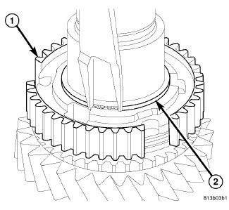
Remove 1-2 synchronizer hub (1) snap ring (2).
NOTE: All snap rings are select fit from the factory, and must be installed in their original location.
-
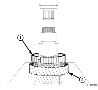
Remove 1-2 synchronizer hub (1), synchronizer rings and second gear (2) off shaft with a press. Place second gear (2) on press plates and press shaft through 1-2 synchronizer hub (1), synchronizer rings and second gear (2)
COUNTERSHAFT
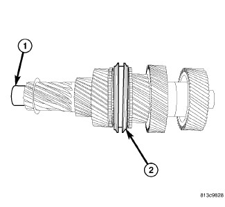 |
The countershaft (1) and 3-4 synchronizer (2) are serviced as an assembly only .
FRONT HOUSING
 |
-
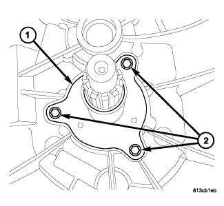
Remove input shaft retainer (1) bolts (2) and remove retainer.
-
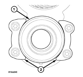
Remove countershaft bearing (1) retainer (2) bolts and remove retainers.
-
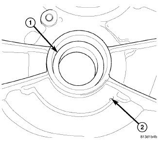
Remove countershaft bearing (1) from housing (2) with a hammer and driver.
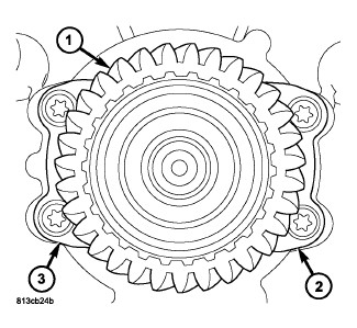
- Remove input shaft (1) bearing retainer (2, 3) bolts and remove retainers.
-
Remove input shaft and bearing from housing with a dead blow hammer.
-
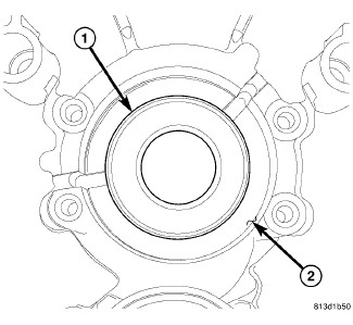
Remove input shaft seal (1) from housing (2) with a hammer and driver.
INPUT SHAFT
 |
-
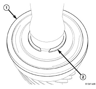
Remove input shaft bearing (1) snap ring (2).
NOTE: All snap rings are select fit from the factory, and must be installed in their original location.
-
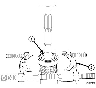
Remove input shaft bearing (1) with Splitter 1130 (2) and press. Place splitter around bearing retainer lip.
REAR HOUSING
 |
-
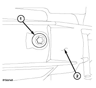
Remove reverse idler gear shaft bolt (1) from housing (2).
-
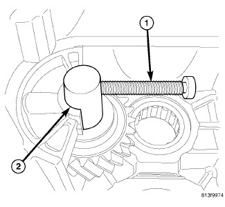
Thread idler gear shaft bolt (1) into the shaft (2). Then work shaft (2) out of the idler gear.
-
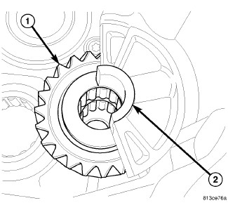
Remove reverse idler gear (1) shaft support (2).
-
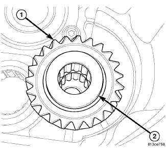
Remove reverse idler gear (1) thrust washer (2).
-
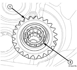
Remove reverse idler gear (1) and bearing (2).
-
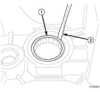
Break plastic countershaft roller bearing cage (1) with a screw driver (2). Then remove cage and roller bearing.
-
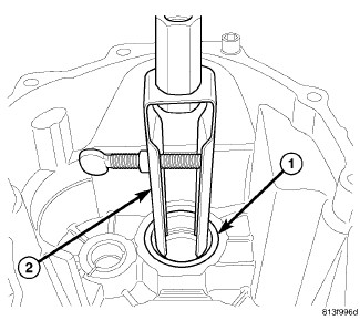
Remove countershaft roller bearing shell (1) from the rear housing with Remover 7794-A (2) and Slide Hammer C-637 .
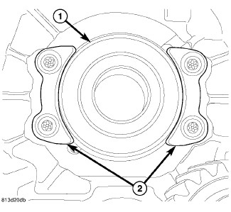
- Remove mainshaft bearing (1) retainer (2) bolts and remove retainers.
-
Remove bearing from housing with a hammer and driver.
CLEANING
Clean gears, shafts, shift components and transmission housings with a standard parts cleaning solvent. Do not use acid or corrosive base solvents. Dry all parts except bearings with compressed air.
Clean shaft bearings with a mild solvent such as Mopar™ degreasing solvent or similar solvents. Do not dry the bearings with compressed air. Allow the bearings to either air dry or wipe them dry with clean shop towels.
INSPECTION
 |
| NOTE: |
Minor corrosion, nicks, or pitting can be smoothed with 400 grit emery and polished out with crocus cloth. |
Bearings: Inspect for worn, cracked, flat-spotted or brinnelled.
Gears: Inspect for worn, chipped or cracked teeth. Inspect bearing surfaces for ware or flat-spotted.
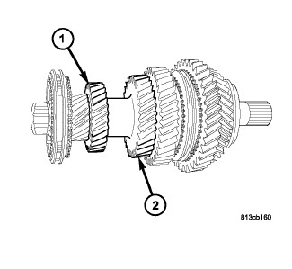
Mainshaft: Inspect for worn splines, snap ring grooves and threads. Inspect bearing surfaces for ware or flat-spotted.Third gear (1) and fourth gear (2) are serviced with mainshaft only.
|
Countershaft: Inspect for worn, chipped or cracked teeth. Inspect bearing surfaces (1) for wear or flat-spots. Inspect 3-4 synchronizer assembly (2).The countershaft is serviced as an assembly.
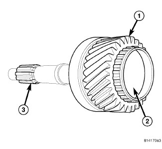 |
Input Shaft: Inspect for worn, chipped or cracked teeth (1). Inspect bearing surface (2) for wear or flat-spots. Inspect for worn splines (3).
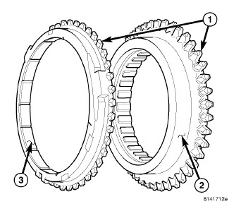 |
Synchronizer components: Inspect for worn, chipped or cracked teeth (1) and burned friction surface (2) or flaking off friction material (3). Synchronizers are serviced as an assembly. 3-4 synchronizer assembly is serviced with countershaft.
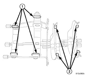 |
Shift forks: Inspect shift forks and shoes (1) for wear and distortion. Check fit of fork shoes in synchronizer sleeve to ensure parts fit and work smoothly, replace if necessary. If shift fork pads (2) are worn, the shift fork must be replaced.
Housing/Tail housing: Inspect sealing and mating surfaces are free of burrs and nicks. Inspect alignment dowels are tight and in good condition.
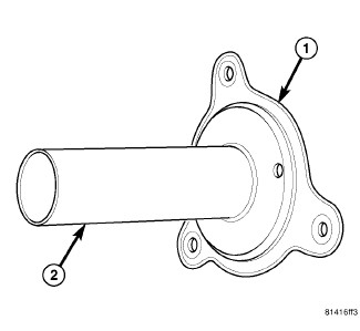 |
Input Shaft Retainer: Inspect retainer (1) release bearing slide surface (2).
ASSEMBLY
MAINSHAFT
 |
- Place mainshaft in Fixture 9648 mounted in a vise.
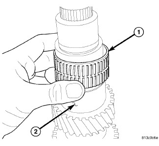
-
Install second gear bearing (1) on mainshaft (2).
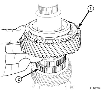
-
Install second gear (1) on bearing (2).
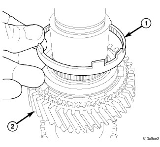
-
Install inner synchronizer friction ring (1) on second gear (2).
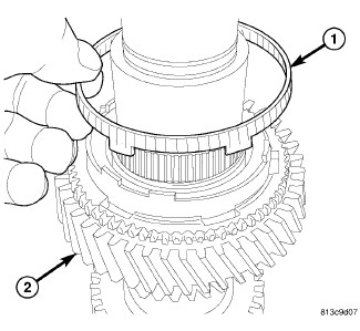
-
Install outer synchronizer friction ring (1) on second gear (2).
-
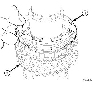
Install synchronizer blocker ring (1) on second gear (2).
-
Install 1-2 synchronizer hub (1) with Installer 8228 (2) and a press. Align hub detent openings with synchronizer rings.
-
Install 1-2 synchronizer hub (1) snap ring (2).
NOTE: Reuse original snap ring or thickest snap ring that will fit.
-
Install 1-2 synchronizer sleeve (1) and push to the bottom of the synchronizer hub (2).
-
Install 1-2 synchronizer detents, springs, and balls (2).
-
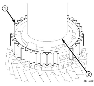
Install first gear blocker ring (1) into synchronizer hub (2).
-
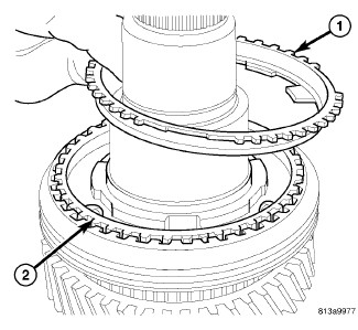
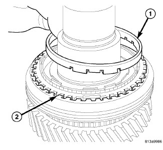
Install first gear outer friction ring (1) into synchronizer hub (2).
-
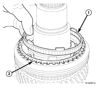
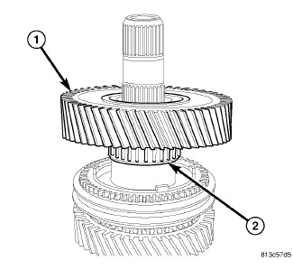
Install first gear inner friction ring (1) into synchronizer hub (2).
-
Install first gear (1) and bearing (2). Then center 1-2 synchronizer sleeve on synchronizer hub.
WARNING: Use welding gloves when handling heated components. Failure to follow these instructions will result in personal injury.
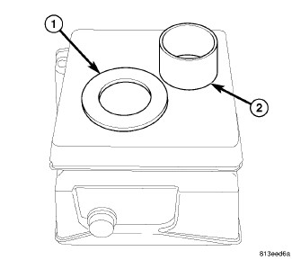
CAUTION: A bearing heater is used to assemble first gear thrust washer (1) and reverse gear bearing race (2). Use only a bearing heater/hot plate and follow manufacture's instructions. Heat components to 100 - 177 Celsius (212° Min - 350° Max Fahrenheit). Never use an open flame to heat components. Never leave components on heater for an extended amount of time. If component is discolored after heating, the component has been overheated and must not be used. Failure to follow these instructions will result in component damage.
-
Heat first gear thrust washer (1) and reverse gear bearing race (2) with bearing heater.
-
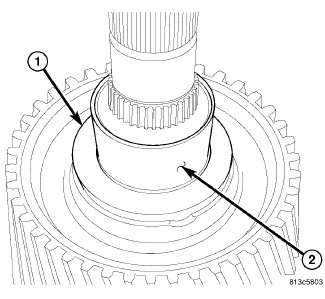
Using welding gloves or tongs, install first gear thrust washer (1) then reverse gear bearing race (2).
-
Install reverse gear (1) and bearing (2).
-
Install reverse gear (1) synchronizer friction ring (2).
-
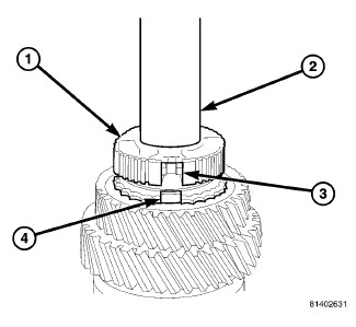
Install reverse gear synchronizer hub (1) on mainshaft with Installer W-262 (2) and a press. Align hub detent opening (3) with friction ring (4) lug.
-
Install reverse gear synchronizer hub (1) detents (2).
- Install reverse gear (1) synchronizer sleeve (2) with tooth points pointing down and center sleeve on synchronizer hub.
-
Remove mainshaft from Fixture 9648 . Turn fixture over in the vise, then install opposite end of mainshaft in the fixture.
-
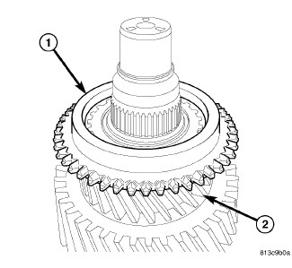
Install sixth gear (1) and bearing (2).
-
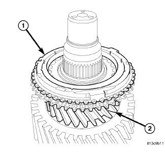
Install sixth gear synchronizer blocker ring (1) on sixth gear (2).
-
Install sixth gear synchronizer friction ring (1) on sixth gear (2).
-
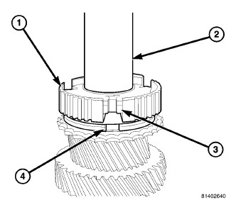
Install 5-6 synchronizer hub (1) with Installer W-262 (2). Align hub detent opening (3) with friction ring lugs (4) and press hub on mainshaft.
NOTE: 5-6 synchronizer hub center, is offset and must be install large offset down.
-
Install 5-6 synchronizer hub (1) snap ring (2).
NOTE: Reuse original snap ring or thickest snap ring that will fit.
-
Install 5-6 synchronizer sleeve on hub (1).
REAR HOUSING
 |
-
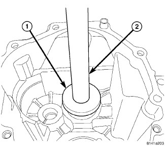
Install countershaft bearing into rear housing with Installer 9643 (1) and Handle C-4171 .
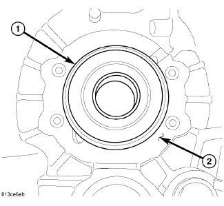
- Install mainshaft bearing (1) into housing (2).
-
Install bearing retainer and tighten bolts to 10 N·m (88 in. lbs.).
-
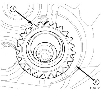
Install reverse idler gear (1) into housing (2).
-
Install idler gear (1) bearing (2) into gear.
-
Install idler gear (1) thrust washer (2) on idler gear.
-
Install idler gear (1) shaft support (2) into housing.
-
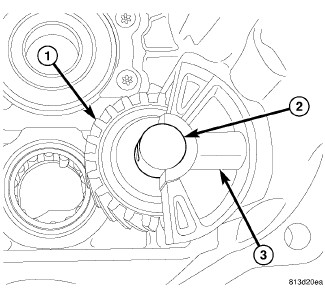
Install idler gear (1) shaft (2) with shaft bolt hole aligned with shaft support hole (3).
-
Install idler gear shaft bolt (1) into the housing (2) and tighten to 20 N.m (15 ft. lbs.).
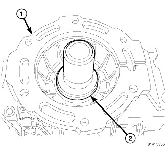
NOTE: Only install the output shaft seal on 4x2 applications at this point. 4x4 seal will be installed later in the procedure.
-
Install 4x2 output shaft seal into rear housing with Installer 9635 and Installer 6448A .
INPUT SHAFT
 |
-
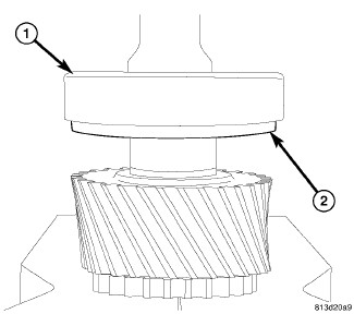
Install input shaft bearing (1) on input shaft with the bearing retainer lip (2) facing fifth gear.
-
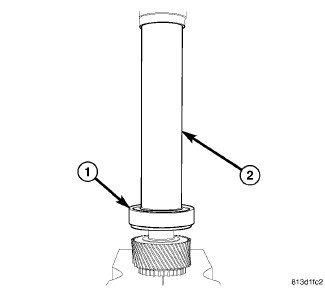
Install input shaft bearing (1) with Installer 6448A (2) and a press.
- Install input shaft bearing (1) snap-ring (2).
| NOTE: |
Reuse original snap ring or thickest snap ring that will fit. |
FRONT HOUSING
 |
-
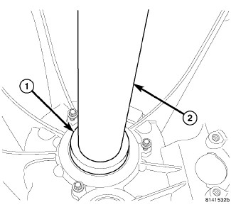
Install input shaft seal with Installer 9635 (1) and Installer 6448A (2).
-
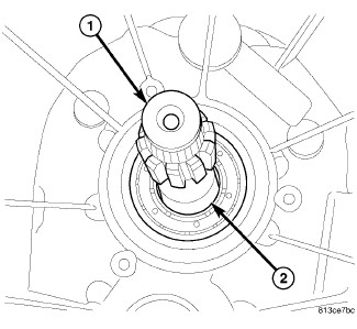
Install input shaft (1) with bearing (2) into housing.
-
Install input shaft (1) bearing retainers (2, 3) and tighten bolts to 10 N·m (88 in. lbs.).
-
Install input shaft retainer (1) and tighten bolts (2) to 9 N·m (80 in. lbs.).
-
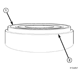
Install countershaft bearing (1) into housing with bearing retainer lip (2) facing up.
-
Install countershaft bearing (1) retainers (2) and tighten bolts to 10 N·m (88 in. lbs.).
FINAL ASSEMBLY
 |
-
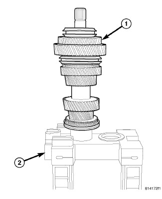
Install mainshaft (1) onto Build Fixture 9633 (2).
-
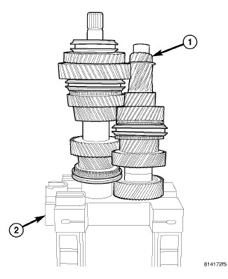
Install countershaft (1) onto Build Fixture 9633 (2).
-
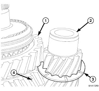
Install oil slinger (3) on countershaft (2) between reverse (1) and first gear (4).
-
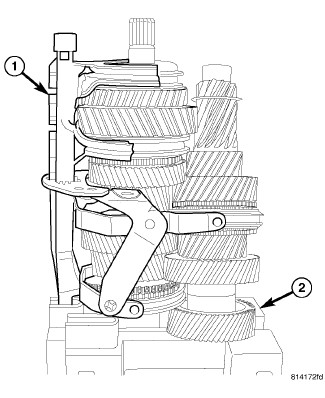
Install shift rails and forks (1) onto Fixture 9633 (2) and countershaft/mainshaft .
-
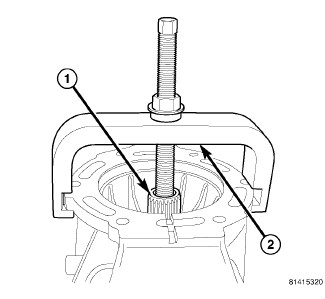
Install rear housing on mainshaft (1) with Installer 9636 (2).
- Remove rear housing with mainshaft, countershaft and shift rails from fixture. Set assembly on rear housing with shafts pointing up.
-
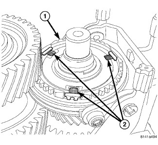
Install 5-6 synchronizer hub (1) detents, springs, and balls (2).
-
Install fifth gear synchronizer friction ring (1) on 5-6 synchronizer hub (2).
-
Install fifth gear blocker ring (1) on 5-6 synchronizer hub (2). Then hold blocker ring and center synchronizer sleeve.
-
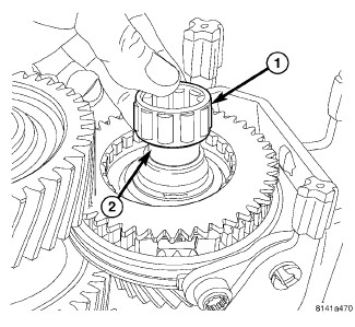
Install input shaft roller bearing (1) on mainshaft (2).
- Apply Mopar® Lock and Seal Adhesive to shift rail support plate bolts.
-
Install shift rail (1) support plate (2) bolts and tighten to 8 N·m (71 in. lbs.).
- Apply MOPAR® Gasket Maker to front housing.
-
Install front housing (1) on rear housing (2) and tighten bolts to 28 N·m (20 ft. lbs.).
-
Install output shaft (1) snap ring (2) 4x4 only.
-
Install output shaft (1) seal (2) in rear housing with Installer 9638 .
-
Through the shift tower opening (1) move two shift rails (2) forward to lock the transmission in two gear.
-
Install countershaft bolt (1) into the front housing (2) and tighten to 100 N·m (74 ft. lbs.).
-
Install countershaft plug (1) in front housing (2) with Installer 7828-A and Handle C-4171 .
- Move shift rails to neutral.
-
To prevent plugging the transmission vent, apply just a thin film of MOPAR® Gasket Maker to shift tower mating surface.
NOTE: If replacing the transmission. Do not reuse old shift tower. Use new shift tower that comes with new transmission.
-
Install shift tower (1) and tighten bolts (2) to 14 N·m (10 ft. lbs.).
-
Install back up lamp switch (1) and bolt (2).
INSTALLATION
 |
-
Apply light coat of Mopar high temperature bearing grease or equivalent to contact surfaces of following components:
- release fork ball stud
- release bearing slide surface
- input shaft splines
- release bearing bore
- propeller shaft slip yoke.
-
pilot bearing
- Clean transmission front housing mounting surface.
- Check the alignment of the clutch (Refer to 06 - Clutch/DISC, Clutch - Installation) .
- Support and secure transmission to jack.
-
Install transmission on engine. Tighten bolts to 50 N·m (37 ft. lbs.).
CAUTION: Do not allow release lever plunger to pivot more than 2° in either direction in the slave cylinder bore. Allowing the plunger to pivot more than 2° in the bore will cause fluid to bypass the seal and result in fluid leakage.
NOTE: Pull the clutch release lever toward the slave cylinder opening to insure proper seating of the slave cylinder plunger to the release lever pocket.
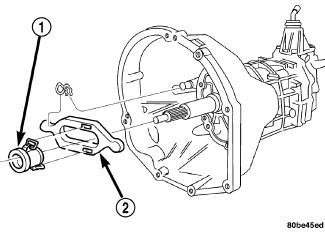
- Install slave cylinder (3) in transmission.
-
Install hydraulic line (2) and with bracket to slave cylinder.
NOTE: Verify O-ring is on hydraulic line.
- Install clutch slave cylinder (2) and tighten mounting nuts (1) to 23 N·m (17 ft. lbs.).
- Bleed hydraulic system. (Refer to 06 - Clutch - Standard Procedure) .
-
Install the starter. (Refer to 08 - Electrical/8F - Engine Systems/Starting/STARTER - Installation)
.
- Install transmission mount bolts and tighten to 47 N·m (35 ft. lbs.).
- Install transmission crossmember (1) and tighten bolts to 47 N·m (35 ft. lbs.) (Refer to 13 - Frame and Bumpers/Frame/CROSSMEMBER - Installation) .
- If equipped, install transfer case (Refer to 21 - Transmission and Transfer Case/Transfer Case - Installation) .
- Route and attach wiring harnesses to clips on case.
-
Install vents and electrical connectors.
-
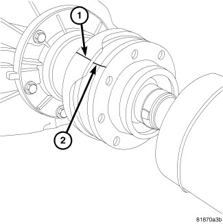
Install propeller shaft/shafts with reference marks (1, 2) aligned (Refer to 03 - Differential and Driveline/Propeller Shaft/SHAFT, Drive - Installation)
.
-
Install exhaust system. (Refer to 11 - Exhaust System/CONVERTER, Catalytic - Installation)
-
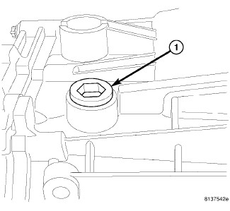
Remove fill plug (1) and fill transmission with lubricant. (Refer to 04 - Vehicle Quick Reference/Capacities and Recommended Fluids - Specifications)
.
- Install skid plates.
-
Lower vehicle.
-
Install shift lever (2) and tighten bolt to 4 N·m (33 in. lbs.) (Refer to 21 - Transmission and Transfer Case/Manual/LEVER, Shift - Installation)
.
- Connect negative battery cable.
SPECIAL TOOLS
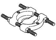 |
1130 - Splitter, Bearing/Gear Originally Shipped In Kit Number(s) 6745, 6947, 6949, 9202, 9202A-CAN, 9202CC, 9299. |
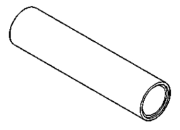 |
6448A - Installer, Bearing/Gear Originally Shipped In Kit Number(s) 6947, 8667, 8837, 8867. |
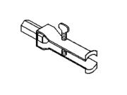 |
7794-A - Remover, Seal Originally Shipped In Kit Number(s) 6645. |
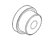 |
7828-A - Installer, Bearing Originally Shipped In Kit Number(s) 9960. |
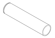 |
8228 - Installer, Bearing Originally Shipped In Kit Number(s) 8295, 8295CC, 8636. |
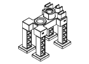 |
9633 - Fixture, Pallet Originally Shipped In Kit Number(s) 9526, 9575, 9633, 9960. |
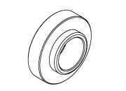 |
9635 - Installer, Seal Originally Shipped In Kit Number(s) 9526, 9575, 9960. |
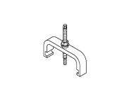 |
9636 - Remover/Installer, Housing Originally Shipped In Kit Number(s) 9526, 9575, 9960. |
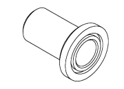 |
9638 - Installer, Seal Originally Shipped In Kit Number(s) 9526, 9575, 9960. |
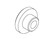 |
9643 - Installer, Bearing Originally Shipped In Kit Number(s) 9526, 9575, 9923, 9924, 9960. |
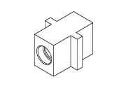 |
9648 - Fixture Originally Shipped In Kit Number(s) 9526, 9575, 9960. |
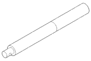 |
C-4171 - Driver Handle, Universal Originally Shipped In Kit Number(s) 9202, 9202A-CAN, 9202CC, 9299, 9299CC, 9299CC, 9300A-CAN. |
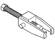 |
C-4333A-1 - Puller, Pulley |
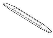 |
C-4755 - Trim Stick Originally Shipped In Kit Number(s) 9299, 9299CC, 9299CC, 9300A-CAN. |
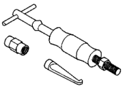 |
C-637 - Slide Hammer, Universal Originally Shipped In Kit Number(s) 9202. |
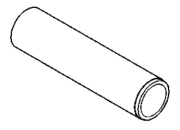 |
W-262 - Installer, Bearing Originally Shipped In Kit Number(s) 8418. |