24 - Heating and Air Conditioning
- DESCRIPTION
- OPERATION
- A/C PERFORMANCE
- HEATER PERFORMANCE
- STANDARD PROCEDURE - A/C EVAPORATOR CLEANING
- A/C SYSTEM
- FASTENER TORQUE
- SPECIAL TOOLS
DESCRIPTION
| NOTE: |
LHD model shown. RHD model similar. |
An electric Manual Temperature Control (MTC) single zone heating-A/C system and an Automatic Temperature Control (ATC) single zone type heating-A/C system are available on this vehicle.
To maintain the performance level of the Heating, Ventilation and Air Conditioning (HVAC) system, the engine cooling system must be properly maintained. The use of a bug screen is not recommended. Any obstructions in front of the radiator or A/C condenser will reduce the performance of the A/C and engine cooling systems.
The engine cooling system includes the radiator, thermostat, radiator hoses and the engine coolant pump. Refer to 7 - Cooling for more information before opening or attempting any service to the engine cooling system.
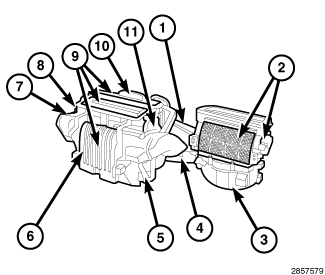 |
All vehicles are equipped with a common HVAC housing (1). The heating-A/C system combines A/C, heating, and ventilating capabilities in a single unit mounted within the passenger compartment beneath the instrument panel. The HVAC housing includes:
- Recirculation-air door and actuator (2)
- Blower motor (3)
- Blower motor power module (4)
- Heater core (5)
- Blend-air door (6)
- Blend door actuator (7)
- Evaporator temperature sensor (A/C only) (8)
- Mode-air doors (9)
- A/C evaporator (A/C only) (10)
- Mode door actuator (11)
On heater-only systems, the A/C evaporator is omitted from the HVAC housing and is replaced with an air restrictor plate.
| NOTE: |
An electric positive temperature coefficient (PTC) heater is used on vehicles when equipped with the 2.8L diesel engine. The PTC heater unit compensates for the lower engine coolant temperatures produced by the diesel engine. The PTC heater unit is mounted in the HVAC air distribution housing, downstream of the heater core. For more information, (Refer to 24 - Heating and Air Conditioning/Cabin Heater/UNIT, Heater - Description) . |
Based upon the system mode selected, conditioned air can exit the standard heater-only or optional heater-A/C housing through one or a combination of the three main housing outlets: defrost, panel or floor. The defrost and panel outlets are located on the top of the HVAC air distribution housing and the floor outlets are located on each side of the distribution housing. Once the conditioned air exits the HVAC housing, it is further directed through molded plastic ducts to the various outlets within the vehicle interior. These outlets and their locations are as follows:
- Defroster Outlet - A single large defroster outlet is located in the center of the instrument panel, near the base of the windshield.
- Side Window Demister Outlets - There are two side window demister outlets, one is located at each outboard end of the instrument panel top cover, near the belt line at the A-pillars.
- Panel Outlets - There are four panel outlets in the instrument panel, one located near each outboard end of the instrument panel facing the rear of the vehicle and two near the center of the instrument panel.
- Front Floor Outlets - There are two front floor outlets, one located on each side the floor panel center tunnel behind the instrument panel.
OPERATION
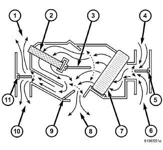
Both the Manual Temperature Control (MTC) and the Automatic Temperature Control (ATC ) heating-A/C systems are blend-air type systems. In a blend-air system, a blend-air door controls the amount of conditioned air that is allowed to flow through, or around the heater core. The temperature control determines the discharge air temperature by operating the blend-air door. This design allows almost immediate control of output air temperature.
 |
| NOTE: |
Typical blend-air type HVAC system shown. |
The heating-A/C system pulls outside (ambient) air through the fresh air intake (4) located at the cowl panel at the base of the windshield and into the air inlet housing above the Heating, Ventilation and Air Conditioning (HVAC) housing and passes through the A/C evaporator (7). Air flow is then directed either through or around the heater core (2). This is done by adjusting the position of the blend-air door (3) with the temperature control located on the A/C-heater control in the instrument panel. Air flow is then directed out the floor outlet (8), instrument panel outlet (10) or the defroster outlet (1) in various combinations by adjusting the position of the mode-air doors (9 and 11) using the mode control located on the A/C-heater control. The temperature and mode control uses electrical actuators to operate the air doors.
The velocity of the air flow out of the outlets can be adjusted with the blower speed control located on the A/C-heater control.
| NOTE: |
Recirculation mode will not operate when in the Floor, Mix or Defrost position and the recirculation indicator lamp will not illuminate. |
The fresh air intake can be shut off by pressing the Recirculation button on the A/C-heater control. This will operate the electrically actuated recirculation-air door (5), which closes off the fresh air intake. With the fresh air intake closed, the conditioned air within the vehicle is pulled back into the HVAC housing through the recirculation air intake (6) located within the passenger compartment.
When equipped, the A/C compressor can be engaged by pressing the A/C (snowflake) button on the MTC A/C-heater control, or is automatically engaged on the ATC system, when set temperatures require conditioned air cooling. On both systems, the A/C compressor will automatically engage when in any Mix to Defrost position. This will remove heat and humidity from the air before it is directed through or around the heater core.
The defroster outlet receives airflow from the HVAC housing through the molded plastic defroster duct, which is secured to the top of the instrument panel. The airflow from the defroster outlet is directed by fixed vanes in the defroster outlet grille and cannot be adjusted.
The side window demister outlets receive airflow from the HVAC housing through the defroster duct and molded plastic demister ducts. The airflow from the side window demister outlets is directed by fixed vanes in the demister outlet grilles and cannot be adjusted. The side window demister outlet grilles are integral to the instrument panel cover and direct air from the HVAC housing through the outlets on the top corners of the instrument panel. The demisters operate when the mode control is set in any Floor to Defrost position.
The panel outlets receive airflow from the HVAC housing through the center air distribution duct and molded plastic panel outlet ducts. The airflow direction from each of the panel outlets can be adjusted by rotating the outlet and/or moving the shutters which are integral to each outlet. Airflow can be turned on or off through each outlet by closing the shutters completely.
The front floor receives airflow from the HVAC housing through molded plastic front floor ducts which are secured to each side of the HVAC air distribution housing. The airflow direction from the floor outlets can not be adjusted.
A/C PERFORMANCE
The A/C system is designed to provide the passenger compartment with low temperature and low humidity air. The A/C evaporator, located in the HVAC housing is cooled to temperatures near the freezing point. As warm damp air passes over the fins of the A/C evaporator, the air transfers its heat to the refrigerant in the evaporator coils and the moisture in the air condenses on the evaporator fins. During periods of high heat and humidity, an A/C system will be more effective in the Recirculation mode (max-A/C). With the system in the Recirculation mode, only air from the passenger compartment passes through the A/C evaporator. As the passenger compartment air dehumidifies, the A/C system performance levels rise.
Humidity has an important bearing on the temperature of the air delivered to the interior of the vehicle. It is important to understand the effect that humidity has on the performance of the A/C system. When humidity is high, the A/C evaporator has to perform a double duty. It must lower the air temperature, and it must lower the temperature of the moisture in the air that condenses on the evaporator fins. Condensing the moisture in the air transfers heat energy into the evaporator fins and coils. This reduces the amount of heat the A/C evaporator can absorb from the air. High humidity greatly reduces the ability of the A/C evaporator to lower the temperature of the air.
However, evaporator capacity used to reduce the amount of moisture in the air is not wasted. Wringing some of the moisture out of the air entering the vehicle adds to the comfort of the passengers. Although, an owner may expect too much from their A/C system on humid days. A performance test is the best way to determine whether the system is performing up to design standards. This test also provides valuable clues as to the possible cause of trouble with the A/C system. The ambient air temperature in the location where the vehicle will be tested must be a minimum of 21° C (70° F) for this test.
A/C PERFORMANCE TEST
Review the warnings and cautions
for this system before performing the procedure. Failure to follow
these instructions may result in serious injury or death.
WARNING:
The use of an A/C recycling/charging
station for purposes of determining the actual charge level of an
A/C system is not recommend. Service recycling/charging stations do
not reflect the correct amount of refrigerant charge in the A/C system
after a single “reclaim” cycle. Tests have shown that it takes up
to two or more “reclaim” cycles to remove all of the refrigerant charge,
depending on the equipment being used. Use only the following procedure
for determining the proper charge level.
CAUTION:
| NOTE: |
When connecting the service equipment coupling to the line fitting, verify that the valve of the coupling is fully closed. This will reduce the amount of effort required to make the connection. |
- Check for Diagnostic Trouble Codes (DTCs) using a scan tool. If no DTCs are found in the A/C heater control, Totally Integrated Power Module (TIPM) or Powertrain Control Module (PCM), go to Step #2. If any DTCs are found, repair as required, then proceed to Step #2.
-
Connect a tachometer
and a manifold gauge set or an A/C recycling/charging station.
NOTE: The ambient air temperature of the vehicle and the location where the vehicle will be tested must be a minimum of 21° C (70° F) before performing this test. Also the evaporator temperature sensor must be a minimum of 13° C (55° F) for this test as well. Place the vehicle in the testing area until the temperature within the vehicle reaches a minimum of 21° C (70° F) prior to conducting the A/C Performance Test.
-
Operate the heating
and A/C system under the following conditions.
- Engine at idle and operating temperature
- Doors or windows open
- Transmission in Park or Neutral with parking brake set (depending on application)
- A/C heater controls set to Recirculation mode (max-A/C), full cool, panel mode, high blower and with A/C compressor engaged. If the A/C compressor does not engage, see the A/C System Diagnosis table.
-
Insert a thermometer
in the driver side center panel air outlet and operate the vehicle
a minimum of ten minutes to allow the thermometer temperature to stabilize.
NOTE: This procedure requires the technician to know what the temperature and relative humidity is at the time of the test. The temperature must be combined with the relative humidity to calculate the apparent ambient temperature ("feels like" temperature), when the temperatures are above 21° C (70° F). Use the current ambient temperature and the relative humidity in your location. This information can be obtained from multiple sources, such as the internet or local news media.
-
With the A/C clutch
engaged, compare the air temperature at the center panel outlet and
the A/C compressor discharge pressure (high side) to the A/C Performance
Temperature and Pressure chart. The A/C clutch may cycle, depending
upon the ambient temperature and humidity. If the A/C clutch cycles,
use the readings obtained before the clutch disengaged.
A/C PERFORMANCE TEMPERATURE AND PRESSURE
Ambient Temperature (Apparent)
21° C (70° F)
27° C (80° F)
32° C (90° F)
38° C (100° F)
43° C (110° F)
Air Temperature at Center Panel Outlet
6 -15° C (42 - 59° F)
7 -18° C (45 - 64° F)
9 - 21° C (48 - 69° F)
11 - 22° C (52 - 72° F)
13 - 24° C (56 - 75° F)
A/C High Side Pressure
1034 - 1896 kPa (150 - 275 psi)
1207 - 2068 kPa (175 - 300 psi)
1379 - 2241 kPa (200 - 325 psi)
1551 - 2413 kPa (225 - 350 psi)
1724 - 2241 kPa (250 - 375 psi)
A/C Low Side Pressure
214 - 365 kPa (31 - 53 psi)
248 - 407 kPa (36 - 59 psi)
283 - 476 kPa (41 - 69 psi)
317 - 483 kPa (46 - 70 psi)
359 - 496 kPa (52 - 72 psi)
- If the air outlet temperature fails to meet the specifications in the A/C Performance Temperature and Pressure chart, or if the A/C compressor discharge pressure is high, see the A/C System Diagnosis table.
A/C SYSTEM DIAGNOSIS
|
Condition |
Possible Causes |
Correction |
|---|---|---|
|
Rapid A/C clutch cycling (ten or more cycles per minute) |
1. Low refrigerant system charge |
1. See Refrigerant System Leaks in this group. Test the refrigerant system for leaks. Repair, evacuate and charge the refrigerant system as required |
|
Equal pressures, but the A/C clutch does not engage |
1. No refrigerant in the refrigerant system |
1. See Refrigerant System Leaks in this group. Test the refrigerant system for leaks. Repair, evacuate and charge the refrigerant system as required. |
|
2. Open fuse |
2. See Wiring Information. Check the fuse in the junction block. Repair the shorted circuit or component and replace the fuse as required. |
|
|
3. Inoperative A/C clutch |
3. See A/C Compressor in this group. Test the A/C clutch coil and replace as required. |
|
|
4. Improperly installed or inoperative A/C pressure transducer |
4. See A/C Pressure Transducer in this group. Test the transducer and replace as required. |
|
|
5. Improperly installed or inoperative evaporator temperature sensor |
5. See Evaporator Temperature Sensor in this group. Correctly install or test and replace the sensor as required. |
|
|
6. Inoperative A/C heater control, TIPM or PCM |
6. See Group 28 - DTC Based Diagnostics. Test the A/C heater control, TIPM and PCM. Replace as required. |
|
|
Normal refrigerant pressures, but A/C Performance Test air temperatures at center panel outlet are too high |
1. Excessive refrigerant oil in system |
1. See Refrigerant Oil Level in this group. Recover the refrigerant from the refrigerant system and inspect the refrigerant oil content. Restore the refrigerant oil to the proper level as required. |
|
2. Blend door actuator inoperative |
2. See Blend Door Actuator this group. Test for proper operation. Replace as required. |
|
|
3. Blend door inoperative or sealing improperly |
3. See HVAC Housing in this group. Inspect the blend door for proper operation and sealing. Repair as required. |
|
|
The low side pressure is normal or slightly low, and the high side pressure is too low |
1. Low refrigerant system charge |
1. See Refrigerant System Leaks in this group. Test the refrigerant system for leaks. Repair, evacuate and charge the refrigerant system as required. |
|
2. Refrigerant flow through the A/C evaporator is restricted |
2. See A/C Evaporator in this group. Replace the restricted A/C evaporator as required. |
|
|
3. Inoperative A/C compressor |
3. See A/C Compressor in this group. Replace the compressor as required. |
|
|
The low side pressure is normal or slightly high, and the high side pressure is too high |
1. A/C condenser air flow restricted |
1. See A/C Condenser in this group. Check the A/C condenser for damaged fins, foreign objects obstructing air flow through the condenser fins, and missing or improperly installed air seals. Clean, repair, or replace components as required. |
|
2. Refrigerant flow through the A/C receiver/drier is restricted |
2. See A/C Receiver/Drier in this group. Replace the restricted A/C receiver/drier as required. |
|
|
3. Inoperative radiator cooling fan |
3. See Group 7 - Cooling. Test the radiator cooling fan and replace as required. |
|
|
4. Refrigerant system overcharged |
4. See Refrigerant System Charge in this group. Recover the refrigerant from the refrigerant system. Charge the refrigerant system to the proper level as required. |
|
|
5. Air in the refrigerant system |
5. See Refrigerant System Leaks in this group. Test the refrigerant system for leaks. Repair, evacuate and charge the refrigerant system as required. |
|
|
6. Engine overheating |
6. See Group 7 - Cooling. Test the engine cooling system and repair as required. |
|
|
The low side pressure is too high, and the high side pressure is too low |
1. Accessory drive belt slipping |
1. See Group 7 - Cooling. Inspect the accessory drive belt condition and tension. Replace the accessory drive belt or tensioner as required. |
|
2. Inoperative A/C expansion valve |
2. See A/C Expansion Valve in this group. Test and replace the valve as required. |
|
|
3. Inoperative A/C compressor |
3. See A/C Compressor in this group. Replace the A/C compressor as required. |
|
|
The low side pressure is too low, and the high side pressure is too high |
1. Restricted refrigerant flow through the refrigerant lines |
1. See A/C Liquid Line, Suction Line and Discharge Line in this group. Inspect the refrigerant lines for kinks, tight bends or improper routing. Correct the routing or replace the refrigerant line as required. |
|
2. Restricted refrigerant flow through the A/C expansion valve |
2. See A/C Expansion Valve in this group. Test and replace the valve as required. |
|
|
3. Restricted refrigerant flow through the A/C condenser |
3. See A/C Condenser in this group. Replace the restricted A/C condenser as required. |
HEATER PERFORMANCE
Before performing the following tests, see Group 7 - Cooling for the procedures to check the engine coolant level and flow, engine coolant reserve/recovery system operation, accessory drive belt condition and tension, radiator air flow and the fan drive operation.
Do not remove radiator cap when
engine is hot. Failure to follow this instruction may result in serious
injury.
WARNING:
If vehicle has been run recently, wait 15 minutes before removing the radiator cap. Place a rag over the cap and turn it to the first safety stop. Allow pressure to escape through the overflow tube. When the system pressure stabilizes, remove the cap completely.
MAXIMUM HEATER OUTPUT
Engine coolant is delivered to and from the heater core through two heater hoses. With the engine idling at normal operating temperature, set the temperature control to the full hot position, the mode control to the floor position, and the blower motor control to the highest speed position. Using a test thermometer, check the temperature of the air being discharged at the front floor outlets. Compare the test thermometer reading to the Heater Temperature Reference chart.
HEATER TEMPERATURE REFERENCE
|
Ambient Temperature |
Minimum Floor Outlet Temperature |
||
|---|---|---|---|
|
Celsius |
Fahrenheit |
Celsius |
Fahrenheit |
|
16° |
60° |
54° |
130° |
|
21° |
70° |
56° |
132° |
|
27° |
80° |
57° |
134° |
|
32° |
90° |
58° |
136° |
See Group 7 - Cooling if the heater outlet air temperature is below the minimum specification. Both of the heater hoses should be hot to the touch. The coolant return heater hose should be slightly cooler than the coolant supply heater hose. If the return hose is much cooler than the supply hose, locate and repair the engine coolant flow obstruction in the cooling system.
OBSTRUCTED COOLANT FLOW
Possible locations or causes of obstructed coolant flow are as follows:
- Low coolant level
- Inoperative water pump
- Inoperative thermostat
- Pinched or kinked heater hoses
- Improper heater hose routing
- Plugged heater hoses or supply and return ports at the cooling system connections
- Plugged heater core
If proper coolant flow through the cooling system is verified, and heater outlet air temperature is low, a mechanical problem may exist.
MECHANICAL PROBLEMS
Possible causes of insufficient heat due to mechanical problems are as follows:
- Obstructed cowl air intake
- Obstructed heater system outlets
- Inoperative engine thermostat
- Inoperative blower motor system
- Inoperative A/C-heater control
- Inoperative blend door actuator
- Inoperative, obstructed or improperly installed blend-air door
TEMPERATURE CONTROL
If the heater outlet air temperature cannot be adjusted with the temperature control on the A/C-heater control, the following could require service:
STANDARD PROCEDURE - A/C EVAPORATOR CLEANING
Some vehicle operators may experience a musty odor from the A/C system, primarily at start up in hot and humid climates. This odor may be the result of microbial growth on the cooling coil. During normal A/C system operation, condensation forms in and around the A/C cooling coil. When airborne pollutants mix with this condensation, bacteria and fungi growth begins and odor may result.
If the vehicle operator experiences a musty odor when operating the A/C system, perform the following procedure.
Always use eye protection, rubber
gloves and protective clothing when performing the following procedure.
Avoid continuous breathing of vapors from evaporator coil cleaning
and sealing fluids. Avoid contact with skin and eyes. Failure to follow
these instruction may result in possible serious or fatal injury.
WARNING:
- On models equipped with a cabin air filter, remove the filter and inspect for dirt and debris (Refer to 24 - Heating and Air Conditioning/Distribution/FILTER, Cabin Air - Removal) . Discard the used cabin filter if required.
- Remove the cowl panel cover (refer to 23 - Body/Exterior for more information).
- Clean any dirt and debris that may be present at the HVAC fresh air inlet screen and at the top of the cowl panel.
- Install the cowl panel cover.
- Raise and support the vehicle.
- Inspect the evaporator drain hose or tube (depending on application) for foreign material that may be blocking the drain and repair as necessary.
- Once drain operation has been verified;
- Lower the vehicle.
- Place a protective cover over the front passenger side floor and seat area.
- Remove the blower motor (Refer to 24 - Heating and Air Conditioning/Distribution/MOTOR, Blower - Removal) .
- Remove the blower motor power module (Refer to 24 - Heating and Air Conditioning/Controls/MODULE, Power - Removal) .
- Clean any dirt and debris that may be present inside the HVAC blower motor housing and all readily accessible areas inside the HVAC housing. If necessary, use a vacuum with a small flexible hose, and take caution not to damage the evaporator core fins.
- Using PSE Flex Spray Delivery Tool 534-62637 or equivalent, completely coat the entire surface of A/C evaporator with three bottles of Mopar® Cooling Coil Cleaner through the blower motor and power module or resistor openings. Be sure to use all of the coil cleaner in each container.
- Allow the vehicle to sit for 30 minutes.
-
Raise and support the
vehicle.
WARNING: Excess cooling coil cleaner will drain from the evaporator housing when the clamp, cap or plug is removed from the evaporator drain hose or tube. Always use eye protection, rubber gloves and protective clothing. Avoid continuous breathing of vapors from evaporator coil cleaning fluid. Avoid contact with skin and eyes. Failure to follow these instruction may result in possible serious or fatal injury.
- Remove the previously installed clamp, cap or plug from the evaporator drain hose or tube and allow excess coil cleaner to drain from the HVAC housing.
- Lower the vehicle.
- Refill the three empty coil cleaner bottles with clean tap water.
- Using PSE Flex Spray Delivery Tool 534-62637 or equivalent, completely rinse the entire surface of A/C evaporator with the three bottles of clean tap water through the blower motor and power module openings. Be sure to use all of the water in each container.
- Install the blower motor (Refer to 24 - Heating and Air Conditioning/Distribution/MOTOR, Blower - Installation) .
- Install the blower motor power module (Refer to 24 - Heating and Air Conditioning/Controls/MODULE, Power - Installation) .
- Disconnect the wire harness connector from the A/C compressor to disable compressor operation (Refer to 24 - Heating and Air Conditioning/Plumbing/COMPRESSOR, A/C - Removal) .
- Start the engine
- Adjust all the windows so they are open approximately 8 mm (0.5 in.).
- Set the A/C heater controls to the following:
- Allow the vehicle to run for 20 minutes.
- Turn the engine off.
- Raise and support the vehicle.
- Inspect the evaporator drain hose or tube (depending on application) for foreign material that may have blocked the drain during evaporator coil cleaning and repair as necessary.
- Once drain operation has been verified;
- Lower the vehicle.
- Remove the blower motor (Refer to 24 - Heating and Air Conditioning/Distribution/MOTOR, Blower - Removal) .
- Remove the blower motor power module (Refer to 24 - Heating and Air Conditioning/Controls/MODULE, Power - Removal) .
-
Using PSE Flex Spray
Delivery Tool 534-62637 or equivalent, completely coat the entire
surface of A/C evaporator with one bottle of Mopar® Cooling Coil Coating
through the blower motor and power module openings. Be sure to use
all of the coil coating in the container.
NOTE: Be sure to thoroughly clean out the spray delivery tool with warm water once coil coating is complete to prevent damage to the tool.
- Refill the empty bottles with clean warm tap water and completely rinse out the PSE Flex Spray Delivery Tool 534-62637, or equivalent.
- Allow the vehicle to sit for 30 minutes.
- Install the blower motor (Refer to 24 - Heating and Air Conditioning/Distribution/MOTOR, Blower - Installation) .
- Install the blower motor power module (Refer to 24 - Heating and Air Conditioning/Controls/MODULE, Power - Installation) .
-
Raise and support the
vehicle.
WARNING: Excess cooling coil coating will drain from the evaporator housing when the clamp, cap or plug is removed from the evaporator drain hose or tube. Always use eye protection, rubber gloves and protective clothing. Avoid continuous breathing of vapors from evaporator coil sealing fluid. Avoid contact with skin and eyes. Failure to follow these instruction may result in possible serious or fatal injury.
- Remove the previously installed clamp, cap or plug from the evaporator drain hose or tube and allow excess coil coating to drain from the HVAC housing.
- Lower the vehicle.
- Start the engine
- Adjust all the windows so they are open approximately 8 mm (0.5 in.).
- Set the A/C heater controls to the following:
- Allow the vehicle to run for 20 minutes.
- Turn vehicle off.
- Remove protective cover from front passenger side floor and seat area.
- On models equipped with a cabin air filter, install the filter (Refer to 24 - Heating and Air Conditioning/Distribution/FILTER, Cabin Air - Installation) .
- Connect the wire harness connector to the A/C compressor (Refer to 24 - Heating and Air Conditioning/Plumbing/COMPRESSOR, A/C - Installation) .
- Verify proper heating and A/C system operation.
A/C SYSTEM
|
Item |
Description |
Notes |
|---|---|---|
|
A/C Compressor |
Zexel DKS-17DS - 2.8L Diesel Engine |
VC-46 PAG oil |
|
Visteon RS-18 - 3.6L Engine |
||
|
A/C Clutch Air Gap |
0.30 - 0.60 mm (0.012 - 0.024 in.) |
2.8L Diesel Engine |
|
0.35 - 0.65 mm (0.014 - 0.025 in.) |
3.6L Engine |
|
|
A/C Clutch Coil Draw |
3.3 amps Max @ 12V ± 0.5V @ 21° C (70° F) |
2.8L Diesel Engine |
|
4.0 amps Max @ 12V ± 0.5V @ 21° C (70° F) |
3.6L Engine |
|
|
A/C Clutch Coil Resistance |
4.0 - 4.4 ohms @ 21° C (70° F) |
2.8L Diesel Engine |
|
3.0 - 4.0 ohms @ 21° C (70° F) |
3.6L Engine |
|
|
Freeze-up Control |
Evaporator Temperature Sensor |
HVAC housing mounted - input to Powertrain Control Module (PCM) |
|
High PSI Control |
A/C Pressure Transducer |
Refrigerant line mounted - input to PCM - PCM disengages compressor clutch above 4.519 volts |
|
High Pressure Relief Valve |
A/C Compressor mounted - opens at a discharge pressure over 3430 - 3930 kPa (497 - 570 psi) |
|
|
Low PSI Control |
A/C Pressure Transducer |
Refrigerant line mounted - input to PCM - PCM disengages compressor clutch below 0.451 volts |
|
R-134a Refrigerant Charge Capacity |
2.8L Engine =510g (1.13 lbs) 3.6L Engine = 624g (1.38 lbs) |
Also see A/C Underhood Specification Label located in the engine compartment |
FASTENER TORQUE
|
Description |
N·m |
Ft. Lbs. |
In. Lbs. |
|---|---|---|---|
|
All Screws NOT Listed Below |
1.2 |
– |
10 |
|
A/C Compressor Bolts |
Specific fastener placement and torque pattern required (Refer to 24 - Heating and Air Conditioning/Plumbing/COMPRESSOR, A/C - Installation) . |
||
|
A/C Compressor Clutch Coil Screws |
5 |
– |
44 |
|
A/C Compressor Shaft Bolt |
20 |
– |
177 |
|
A/C Compressor Coil Connector Bracket Screw |
4.3 |
– |
38 |
|
A/C Condenser to Radiator Bolts |
5 |
– |
45 |
|
A/C Heater Control Screws |
2 |
– |
17 |
|
Air Inlet Housing to Instrument Panel Support Bolts |
4 |
– |
35 |
|
Blend Door Lever Screw |
0.6 |
– |
5 |
|
Discharge Line to Condenser Nut |
23 |
17 |
– |
|
Discharge Line to Compressor Nut |
23 |
17 |
– |
|
Expansion Valve Bolts |
11 |
– |
97 |
|
HVAC Housing to Instrument Panel Support Bolts |
4 |
– |
35 |
|
Liquid Line to Condenser Nut |
23 |
17 |
– |
|
Mode Door Cam Screw |
0.6 |
– |
5 |
|
Receiver/Drier to Condenser Bolt |
22 |
16 |
– |
|
Suction Line to Compressor Nut |
23 |
17 |
– |
|
Suction and Liquid Lines to Expansion Valve Nut |
20 |
– |
177 |
SPECIAL TOOLS
 |
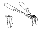
6801 - Terminal Probe Originally Shipped In Kit Number(s) 10190. |
 |
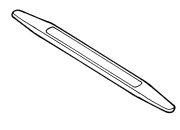
9764 - Pliers, A/C Snap Ring Originally Shipped In Kit Number(s) 9909. |
 |
C-4755 - Trim Stick Originally Shipped In Kit Number(s) 9299, 9299CC, 9299CC, 9300A-CAN. |