P0685-AUTO SHUTDOWN RELAY CONTROL CIRCUIT
For a complete wiring diagram, refer to the Wiring Information.
-
When Monitored:
When the ignition is turned off, during after-run mode of operation.
-
Set Condition:
The Powertrain Control Module (PCM) determines that the ASD Relay has shut off before the AFTER-RUN mode of operation has been completed.
POSSIBLE CAUSES |
|---|
| (K51) ASD RELAY CONTROL CIRCUIT OPEN |
| (K51) ASD RELAY CONTROL CIRCUIT SHORTED TO VOLTAGE |
| (K51) ASD RELAY CONTROL CIRCUIT SHORTED TO GROUND |
| LOSS OF POWERTRAIN CONTROL MODULE POWERS OR GROUNDS |
| ASD RELAY |
| POWERTRAIN CONTROL MODULE (PCM) |
Always perform the Pre-Diagnostic Troubleshooting procedure before proceeding. (Refer to 28 - DTC-Based Diagnostics/MODULE, Powertrain Control (PCM) - Standard Procedure).
| 1. | Turn the ignition on. |
| 2. | With the scan tool, check for additional DTCs. |
Are other DTCs present?
Yes
- Perform the diagnostics for the other DTCs before continuing.
- Perform the POWERTRAIN VERIFICATION TEST. (Refer to 28 - DTC-Based Diagnostics/MODULE, Powertrain Control (PCM) - Standard Procedure).
No
- Go To 2
2. CLEAR CODE AND CHECK IF THE DTC RESETS
| 1. | With the scan tool, erase PCM DTCs. |
| 2. | Perform several ignition key cycles, pausing for at least 10 seconds between each cycle. |
| 3. | Turn the ignition on. |
| 4. | With the scan tool, read PCM DTCs. |
Did this DTC Return?
Yes
- Go To 3
No
- Perform the INTERMITTENT CONDITION diagnostic procedure. (Refer to 28 - DTC-Based Diagnostics/MODULE, Powertrain Control (PCM) - Standard Procedure).
| 1. | Turn the ignition off. |
| 2. | Install a known good relay in place of the ASD Relay. |
| 3. | Turn the ignition on. |
| 4. | With the scan tool, erase PCM DTCs. |
| 5. | Perform several ignition key cycles, pausing for at least 10.0 seconds between each cycle. |
| 6. | Turn the ignition on. |
| 7. | With the scan tool, read PCM DTCs. |
Did this DTC return?
Yes
- Go To 4
No
- Replace the ASD Relay in accordance with the service information.
- Perform the POWERTRAIN VERIFICATION TEST. (Refer to 28 - DTC-Based Diagnostics/MODULE, Powertrain Control (PCM) - Standard Procedure).
4. CHECK PCM POWER AND GROUNDS
| 1. | Using the wiring information, check the PCM battery, ignition feed and ground circuits. |
Were any problem found with the PCM powers and grounds?
Yes
- Repair as necessary.
- Perform the POWERTRAIN VERIFICATION TEST. (Refer to 28 - DTC-Based Diagnostics/MODULE, Powertrain Control (PCM) - Standard Procedure).
No
- Go To 5
5. CHECK THE (K51) ASD RELAY CONTROL CIRCUIT FOR A SHORT TO VOLTAGE
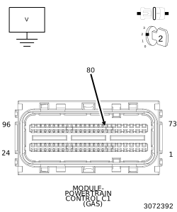 |
| 1. | Reconnect the PCM harness connectors. |
| 2. | Turn the ignition off. |
| 3. | Remove the ASD Relay. |
| 4. | Turn the ignition on. |
| 5. | Measure the voltage an the (K51) ASD Relay Control circuit at terminal 85 of the ASD Relay connector. |
Is there any voltage present?
Yes
- Repair the (K51) ASD Relay Control circuit for a short to voltage.
- Perform the POWERTRAIN VERIFICATION TEST. (Refer to 28 - DTC-Based Diagnostics/MODULE, Powertrain Control (PCM) - Standard Procedure).
No
- Go To 6
6. CHECK THE (K51) ASD RELAY CONTROL CIRCUIT FOR A SHORT TO GROUND
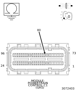 |
| 1. | Turn the ignition off. |
| 2. | Remove the ASD Relay. |
| 3. | Disconnect the PCM C1 harness connector. |
| 4. | Measure the resistance an the (K51) ASD Relay Control circuit at terminal 85 of the ASD Relay connector. |
Is the resistance above 10k Ohms?
Yes
- Go To 7
No
- Repair the (K51) ASD Relay Control circuit for a short to ground.
- Perform the POWERTRAIN VERIFICATION TEST. (Refer to 28 - DTC-Based Diagnostics/MODULE, Powertrain Control (PCM) - Standard Procedure).
7. CHECK THE (K51) ASD RELAY CONTROL CIRCUIT FOR AN OPEN/HIGH RESISTANCE
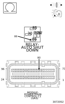 |
| 1. | Measure the resistance of the (K51) ASD Relay Control circuit between the PCM C1 harness connector and the ASD Relay connector. |
Is the resistance below 5.0 Ohms?
Yes
- Repair the ASD Relay Control circuit for an open or high resistance.
- Perform the POWERTRAIN VERIFICATION TEST. (Refer to 28 - DTC-Based Diagnostics/MODULE, Powertrain Control (PCM) - Standard Procedure).
No
- Replace and program the Powertrain Control Module in accordance with the Service Information. (Refer to 08 - Electrical/8E - Electronic Control Modules/MODULE, Powertrain Control - Removal) .
- Perform the POWERTRAIN VERIFICATION TEST. (Refer to 28 - DTC-Based Diagnostics/MODULE, Powertrain Control (PCM) - Standard Procedure).