P0441-EVAP PURGE SYSTEM PERFORMANCE
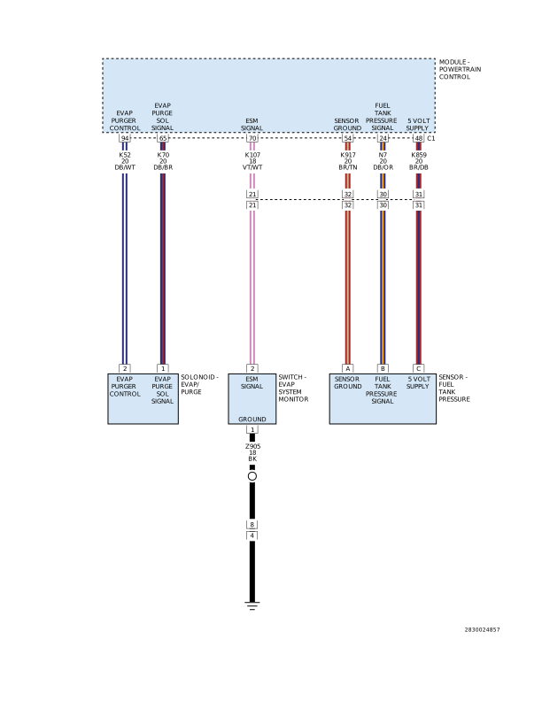
For a complete wiring diagram, refer to the Wiring Information.
 |
Theory of Operation
 |
|
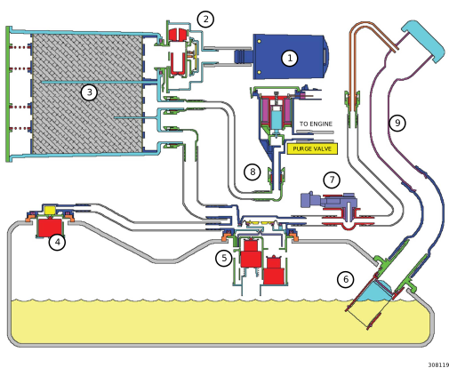
EVAP SYSTEM COMPONENTS |
|
|---|---|
|
CALLOUT |
DESCRIPTION |
|
1 |
Filter |
|
2 |
ESIM Switch |
|
3 |
Evaporative Canister |
|
4 |
Fuel Tank Vent (Check Valve) |
|
5 |
Control Valve |
|
6 |
Inlet Check Valve |
|
7 |
Fuel Tank Pressure Sensor |
|
8 |
To Purge System |
|
9 |
Fuel Fill Tube |
The Evaporative Purge Monitor tests the integrity of the hoses/tube between the throttle body/intake and the fuel tank. The monitor will be enabled under either a Small Leak test or it will run during a Large Leak test (This is when Small Leak test does not pass). During a Small Leak test, the monitor will first evaluate the delta pressure on the Fuel Tank Pressure (FTP) sensor while normal purge control is active. If the monitor does not pass within a calibrated amount of time, then an intrusive monitor will be enabled. This intrusive monitor will ramp in the purge flow to a target amount while evaluating the delta pressure in the entire system. If the delta pressure between purge off and purge on exceeds a calibrated amount, then the monitor will ramp out the purge flow and evaluate the delta pressure between the high flow and the new low flow target. If the delta pressure is less than a calibrated threshold then the monitor will pass.
-
When Monitored:
After the Evaporative System small leak test has passed, with the engine running, ambient temperature between 4°C (40°F) and 35° (95°F), with the engine at idle after a calibrated amount of drive time has accumulated.
-
Set Condition:
If the Powertrain Control Module (PCM) detects that the purge vapor ratio and the ESIM switch closed ratio are below a calculated value, the PCM commands the purge solenoid to flow at a specified rate to update the purge vapor ratio. If the ratio remains below a specified value, a one trip failure is recorded. Two Trip Fault. Three good trips to turn off the MIL.
Possible Causes |
|---|
| FUEL TANK PRESSURE (FTP) SENSOR 5–VOLT SUPPLY OPEN CIRCUIT OR EXCESSIVE RESISTANCE |
| EVAP PURGE SOLENOID VACUUM SUPPLY |
| EVAP PURGE SOLENOID VACUUM SUPPLY |
| EVAPORATIVE PURGE HOSE/TUBE AND FRESH AIR FILTER OBSTRUCTION |
| EVAP PURGE SOLENOID |
| FUEL TANK PRESSURE SENSOR |
| OBSTRUCTED ESIM FRESH AIR FILTER |
| OBSTRUCTED LINE BETWEEN THE FUEL TANK AND CANISTER |
| POWERTRAIN CONTROL MODULE (PCM) |
Always perform the Pre-Diagnostic Troubleshooting procedure before proceeding. (Refer to 28 - DTC-Based Diagnostics/MODULE, Powertrain Control (PCM) - Standard Procedure).
1. VEHICLE HISTORY AND SERVICE BULLETIN INVESTIGATION
| 1. | Ignition on, engine not running. |
| 2. | With the scan tool, select View DTCs and record the related Freeze Frame data if any DTCs are present. |
Choose the following scenario that best applies.
The service bulletin repaired the customer's complaint.
A DTC is present, no service bulletins apply or the service bulletin didn't repair the customer's complaint.
- Go To 2
| NOTE: | If P0443 is set along with this DTC, perform the diagnostic procedure for P0443 before continuing with this test. |
| NOTE: | If the customer is experiencing an early fuel shut off during the fuel filling process along with P0440, P0441 and P0452 setting, you need to check for restrictions in the Evaporative Purge tubes/hoses as well as the Fresh Air Filter before continuing. |
| 1. | Using the scan tool, perform the ESIM FORCED MONITOR TEST. Allow the test to complete. |
| 2. | With the scan tool, select View DTCs. |
| NOTE: | If any other DTC sets, active or pending, perform the diagnostic procedure for that DTC before proceeding with this test. |
Is the DTC Active or Pending at this time?
Yes
- Go To 3
No
- Perform the INTERMITTENT CONDITION diagnostic procedure. (Refer to 28 - DTC-Based Diagnostics/MODULE, Powertrain Control (PCM) - Standard Procedure).
3. CHECK THE FUEL TANK PRESSURE (FTP) SENSOR 5–VOLT SUPPLY CIRCUIT FOR AN OPEN/HIGH RESISTANCE
| NOTE: | Diagnose and repair any system voltage or sensor supply voltage DTC’s before continuing with this test. |
| 1. | Disconnect the FTP Sensor harness connector. |
| 2. | Ignition on, engine not running. |
| 3. | Measure the voltage on the FTP Sensor 5–Volt Supply circuit at the FTP Sensor harness connector. |
Is the voltage between 4.8 to 5.2 volts?
Yes
- Go To 4
No
- Repair the Fuel Tank Pressure Sensor 5–Volt Supply circuit for an open or high resistance.
- Perform the POWERTRAIN VERIFICATION TEST. (Refer to 28 - DTC-Based Diagnostics/MODULE, Powertrain Control (PCM) - Standard Procedure).
4. FUEL TANK PRESSURE (FTP) SENSOR
| 1. | Turn the ignition off. |
| 2. | Reconnect the FTP Sensor harness connector. |
| 3. | Remove the fuel filler cap. |
| 4. | Ignition on, engine not running. |
| 5. | With a voltmeter, back-probe the FTP Sensor Signal circuit at the FTP Sensor harness connector. |
Is the voltage between 2.3 to 2.7 volts?
Yes
- Go To 5
No
- Verify that there is good pin to terminal contact in the Fuel Tank Pressure Sensor and Powertrain Control Module connectors. Replace the FTP Sensor if no problems were found with the connectors. (Refer to 25 - Emissions Control/Evaporative Emissions/SENSOR, Fuel Tank Pressure/Removal) .
- Perform the POWERTRAIN VERIFICATION TEST. (Refer to 28 - DTC-Based Diagnostics/MODULE, Powertrain Control (PCM) - Standard Procedure).
5. EVAP PURGE HOSE/TUBE AND FRESH AIR FILTER OBSTRUCTION
| 1. | Inspect the Evaporative Purge hose/tube for proper routing and installation between the Evap Purge Solenoid and the Fuel Tank and between the Fuel Tank and the Evap Purge Canister. |
| 2. | Make sure the hose/tube and fresh air filter are not damaged, kinked and free from any obstructions. |
Were any problems found?
Yes
- Repair or replace as necessary.
- Perform the POWERTRAIN VERIFICATION TEST. (Refer to 28 - DTC-Based Diagnostics/MODULE, Powertrain Control (PCM) - Standard Procedure).
No
- Go To 6
| NOTE: | After disconnecting the Evap Purge Solenoid vacuum connections, inspect the lines and solenoid for signs of contamination. |
| 1. | Using a hand vacuum pump, apply 10 in Hg to the "CAN" side of the Evap Purge Solenoid. |
| NOTE: | The solenoid should hold vacuum for a minimum of 15 seconds. |
| 2. | Ignition on, engine not running. |
| 3. | With the scan tool, actuate the Evap Purge Solenoid to the ON position. |
| NOTE: | The vacuum should drop when the solenoid is actuated. |
Does the solenoid function as described above?
Yes
- Go To 7
No
- Verify that there is good pin to terminal contact in the Solenoid and the Powertrain Control Module connectors. Replace the Evap Purge Solenoid if no problems were found in the connectors.
- Perform the POWERTRAIN VERIFICATION TEST. (Refer to 28 - DTC-Based Diagnostics/MODULE, Powertrain Control (PCM) - Standard Procedure).
7. POWERTRAIN CONTROL MODULE (PCM)
| 1. | Using the wiring diagram/schematic as a guide, inspect the wiring and connectors between the Evap Purge Solenoid Assembly, ESIM switch and the Powertrain Control Module (PCM). |
| 2. | Look for any chafed, pierced, pinched or partially broken wires. |
| 3. | Look for broken, bent, pushed out or corroded terminals. Verify that there is good pin to terminal contact in the switch, Solenoid and the Powertrain Control Module connectors. |
| 4. | Perform any Technical Service Bulletins that may apply. |
Were there any problems found?
Yes
- Repair as necessary.
- Perform the POWERTRAIN VERIFICATION TEST. (Refer to 28 - DTC-Based Diagnostics/MODULE, Powertrain Control (PCM) - Standard Procedure).
No
- Replace and program the powertrain control module in accordance with the service information. (refer to 08 - electrical/8e - electronic control modules/module, powertrain control - removal) .
- Perform the powertrain verification test. (refer to 28 - dtc-based diagnostics/module, powertrain control (pcm) - standard procedure).