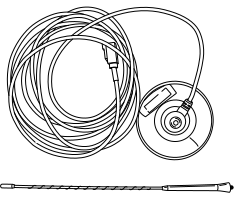
MIT019 MULTI-MEDIA TESTER
MIT019 MULTI-MEDIA
TEST KIT
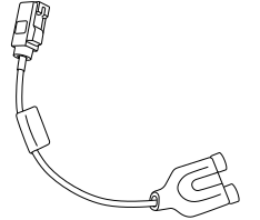
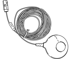
The MIT019 Multi-Media Test kit includes the tester, power outlet
adaptor and a set of test tip cards. The MIT019 can be updated by
connecting to any computer using the USB connector on the tester.
The updates are supported through DealerConnect tech support. If the
test cards are lost, a new set can be downloaded from the tool by
connecting to any supporting computer. The test card information in
the tool can be downloaded in one of 3 languages: English, Spanish
or French.
TO DOWNLOAD
THE TEST CARD INFORMATION:
-
Connect the
MIT019 to a USB port on a computer (which will power the tool and
display the current software version).
-
Press the USB
button on the MIT019.
-
Once the computer
recognizes the MIT019, it will display 3 files available.
-
Select the file
named “MANUAL”.
-
Download the
section required to create the test cards needed.
FOR UPDATES:
-
While holding
down the zero button on the MIT019, connect the MIT019 to a USB port
on a computer (which will power the tool and display the current software
version).
-
If you are a
Chrysler Group LLC Dealership, visit: https://dealerconnect.chrysler.com.
-
If you are a
Non-Chrysler Group LLC Dealership, visit: www.techauthority.com.
-
Locate the MIT019
software update page (verify that a newer software version is available).
-
Download the
update file and run the .exe file.
-
Follow the on-screen
instructions to install the update.
-
Disconnect the
MIT019 USB connection from the computer and the tool is ready to use.
MIT019 MULTI-MEDIA
TESTER FUNCTIONALITY
The MIT019 Multi-Media Test kit was developed to help diagnose
customer concerns with features of the Multi-Media systems in their
vehicles. The purpose of this tool is to simulate the following:
-
A known good
cell phone
-
A known good
media source (Ipod®, Ipad®, or MP3 players)
Using this tester will determine if the cause of concern is related
to a vehicle system concern or the customer`s device being used.
The MIT019 can be used to perform 7 different tests of specific
operations:
-
Operation of
the AUX port
-
Operation of
the USB port for both power and Audio input concerns
-
Bluetooth phone
pairing
-
Bluetooth hands
free calling (send & receive) phone book push test
-
Bluetooth streaming
audio
-
Bluetooth SMS
messaging – send
-
Bluetooth SMS
messaging – receive
| NOTE: |
When testing
functions of the audio/media system, it is important to verify whether
or not the vehicle is equipped with an internal or external Hands
Free Module. In some cases the external Hands Free Module controls
the operation of the external AUX and USB ports along with the Uconnect
functions. |
It is important to determine what system features are supported
by the audio system in the customer’s vehicle and device. For information
on the operation and supported features of the vehicle’s media system,
refer to the flowing websites:
Vehicle websites available to customers and dealership personnel:
-
http://www.dodge.com/en/uconnect
-
http://www.chrysler.com/en/uconnect
-
http://www.jeep.com/en/uconnect
-
http://www.ramtrucks.com/en/uconnect
-
http://www.fiatusa.com/en/BlueAndMe
-
http://www.driveuconnect.com
Vehicle information support websites for dealership personnel only:
-
DealerConnect
-
STAR cases
-
Technical Service
Bulletins
-
wiTECH for radio
updates
The MIT019 was designed to test the following Radio/Multi-Media
systems:
-
2010 – present
NTG4 Radio/Multi-Media systems
-
2011 – present
PowerNet Radio/Multi-Media systems
-
2013 – present
RRM Radio/Multi-Media systems
1.
BELOW ARE THE
7 FUNCTIONALITY TESTS AVAILABLE USING THE MIT019 MULTI-MEDIA TESTER:
| 1. |
AUXILIARY INPUT
JACK TEST
|
| 4. |
BLUETOOTH HANDS
FREE CALLING/PHONEBOOK PUSH TEST
|
| 5. |
BLUETOOTH STREAMING
AUDIO TEST
|
| 6. |
BLUETOOTH SMS MESSAGING
– SEND
|
| 7. |
BLUETOOTH SMS MESSAGING
– RECEIVE
|
2.
AUXILIARY INPUT
JACK TEST
| NOTE: |
This test
is designed to validate the ability of the Audio/Media system to play
audio from a customer’s device that has been connected to the AUX
port on the radio or externally through a UCI (Universal Customer
Interface / Multi-Media) port.
|
| NOTE: |
The AUX port
cannot supply power to a connected device.
|
| 1. |
Connect the USB
and Auxiliary Cable into the vehicle's audio ports.
|
| 2. |
Verify the MIT019
is in AUX Mode.
|
| 3. |
Using the vehicle
controls, place the audio system into AUX (Line In) Mode. (Audio system
may automatically enter into AUX Mode.)
|
Does the Radio play audio from the MIT019?
Yes
-
Audio playback confirms
that the Auxiliary Input is working correctly, no system repairs are
needed at this time.
-
Check the condition
of the customer`s cords and device being used.
-
Check to make sure
the customer`s device and cables are compatible with the vehicle system.
-
Check the customer`s
device for output and volume setting concerns.
-
Check for updates for
the customer`s device relating to the customer`s concern.
No
-
If Audio playback does
not occur, refer to the appropriate Service Information.
-
Check the Multi-Media
ports for damaged connection points or debris in the ports.
-
Check wiring circuits
and connections to the AUX port for concerns.
-
Check for vehicle related
system updates, STAR cases and TSBs related to the customer`s concern.
-
If no updates are available
for the concern, replace the Radio or Hands Free Module in accordance
with the Service Information.
3.
USB INPUT/OUTPUT
TEST
| NOTE: |
This test
is designed to validate the ability of the Audio/Media system to play
audio from a customer’s device that has been connected to the USB
port on the radio or the external USB port (Universal Customer Interface
(UCI) / Multi- Media port). By connecting the MIT019 to the USB ports
it will also determine if the USB port can provide power to a connected
device.
|
| 1. |
Connect the USB
Cable into the vehicle’s USB port.
|
| 2. |
Place the MIT019
into USB Mode.
|
| 3. |
Using the vehicle
controls, place the audio system into USB Mode. (Audio system may
automatically enter into USB Mode.)
|
Does the Radio play audio from the MIT019?
Yes
-
Audio playback confirms
that the USB Input is working correctly, no system repairs are needed
at this time.
-
Check the condition
of the customer`s cords and device being used.
-
Check to make sure
the customer`s device and cables are compatible with the vehicle system.
-
Check the customer`s
device for output and volume setting concerns.
-
Check for updates for
the customer device relating to the customer`s concern.
No
-
If Audio playback does
not occur, refer to the appropriate Service Information.
-
Check the Multi-Media
ports for damaged connection points or debris in the ports.
-
Check wiring circuits
and connections to the USB port for concerns.
-
Check for vehicle related
system updates, Star online cases and TSBs related to the customers
concern.
-
If no updates are available
for the concern, replace the Radio or Hands Free Module in accordance
with the Service Information.
| NOTE: |
The radio
and external USB ports can only supply 5 volts at 500 mAs. Check to
see what the customer’s device requires for operation or charging.
Some vehicles are equipped with a standalone USB charging port that
can supply 5 volts at 1.5 amps. For more information on system operation
and supported features see the vehicle supporting website “For Owners
Page” or the http://www.driveuconnect.com.
|
4.
BLUETOOTH PAIRING
| NOTE: |
This test
is designed to validate the pairing ability of the vehicles Audio/Media
system. Pairing the MIT019 to the vehicle system will simulate the
use of a known good compatible phone to test the system operation.
|
| NOTE: |
Before testing
it is important to check the total number of devices paired to the
vehicles system. Each system has a limit to the number of items that
can be paired to the system. For more information on system operation
and supported features see the vehicle supporting website “For Owners
Page” or the Driveuconnect website at http://www.driveuconnect.com.
|
| NOTE: |
If the customer`s
concern is the vehicle system was working with their device but then
stopped working correctly, verify and perform the following:
-
Check to see
if the device was recently updated.
-
Clear the device
pairing from the system.
-
Reboot the customer`s
device.
-
Re-pair the
device to the vehicle system.
-
Check the operation.
At times, cell providers will update the software or firmware
in the customer`s device (without the customer knowing) causing it
to become out of sync with the vehicle`s system.
|
| NOTE: |
During this
test, use the power outlet adaptor supplied with the MIT019 Multi-Media
Test kit to supply the power and ground to the tester. This will confirm
and demonstrate the Bluetooth connection without anything connected
to the Audio/Media system ports.
|
| NOTE: |
In order for
the tool to function correctly, first plug the MIT019 power supply
adapter into the 12 volt power outlet receptacle and confirm adapter
power LED illuminates. Then connect the MIT019 to the power supply
adapter. |
| 1. |
Connect the power
outlet power adapter into the 12 volt receptacle.
|
| 2. |
Connect the USB
Cable into the Power Outlet Power Adapter. (This assists in showing
the customer that the tool is utilizing a Bluetooth connection.)
|
| 3. |
Place the MIT019
into Bluetooth Mode.
|
| 4. |
Use the vehicle
audio controls to place the audio system into ready to PAIR Mode.
(Audio system may automatically enter into Bluetooth Mode.)
|
| 5. |
Press the PAIR
button on the MIT019 the unit will identify the Vehicle Audio System.
|
| 6. |
When prompted,
enter the Pairing Pin number on the MIT019 then press enter. The MIT019
will Pair and Connect to the vehicle audio system.
|
Does the MIT019 pair to the Audio/Media system?
Yes
-
If the MIT019 pairs
to the system, the Hands Free connection is working correctly, no
part replacement is needed.
-
Check the total number
of devices paired to the customer`s device.
-
Check to make sure
the customer`s device and cables are compatible with the vehicle system.
-
Check to see if the
customer`s device supports the vehicle feature being tested.
-
Check the customer`s
device for concerns related to password locks, phone book transfer
settings and data transfer locks/settings.
-
For more information
on system operation and supported features see the vehicle supporting
website “For Owners Page” or the Driveuconnect website at http://www.driveuconnect.com.
No
5.
BLUETOOTH HANDS
FREE CALLING / PHONE BOOK PUSH TEST
| NOTE: |
This test
is designed to validate the ability of the Audio/Media system to place
and receive phone calls. The MIT019 will change the radio display
to show “MULTI-MEDIA TESTER” to confirm the
phone-book-push
was successful.
|
| NOTE: |
Before testing
it is important to check the total number of devices paired to the
vehicles system. Each system has a limit to the number of items that
can be paired to the system. For more information on system operation
and supported features see the vehicle supporting website “For Owners
Page” or the Driveuconnect website at http://www.driveuconnect.com.
|
| NOTE: |
If the customer`s
concern is the vehicle system was working with their device but then
stopped working correctly, verify and perform the following:
-
Check to see
if the device was recently updated.
-
Clear the device
pairing from the system.
-
Reboot the customer`s
device.
-
Re-pair the
device to the vehicle system.
-
Check the operation.
At times, cell providers will update the software or firmware
in the customer`s device (without the customer knowing) causing it
to become out of sync with the vehicle`s system.
|
| NOTE: |
During this
test use the Power outlet adaptor supplied with the MIT019 Multi-Media
Test kit to supply the power and ground to the tester. This will confirm
and demonstrate the Bluetooth connection without anything connected
to the Audio/Media system ports.
|
| NOTE: |
In order for
the tool to function correctly, first plug the MIT019 power supply
adapter into the 12 volt power outlet receptacle and confirm adapter
power LED illuminates. Then connect the MIT019 to the power supply
adapter. |
| 1. |
Be sure the MIT019
is properly paired.
|
| 2. |
From MIT019 in
Bluetooth Mode, press the CALL button.
|
| 3. |
The vehicle should
announce an incoming call.
|
| 4. |
The media system
will display “MULTI-MEDIA TESTER”, confirming successful push of the
phone book.
|
| 5. |
Using the vehicle
controls, answer the call.
|
| 6. |
Audio playback
will confirm the Hands Free connection is working correctly, no system
part replacement is needed.
|
| 7. |
Using the vehicle
controls, end the call.
|
Does the Media system playback the incoming audio and
display “MULTI-MEDIA TESTER”?
Yes
-
If Audio playback occurs
and the system displays “MULTI-MEDIA TESTER”, the system is working
correctly; no part replacement is needed.
-
Check the total number
of devices paired to the customer`s device.
-
Check to make sure
the customer`s device and cables are compatible with the vehicle system.
-
Check to see if the
customer`s device supports the feature that the customer is trying
to use.
-
Check the customer`s
device for concerns related to password locks, phone book transfer
settings and data transfer locks/settings.
-
For more information
on system operation and supported features see the vehicle supporting
website “For Owners Page” or the Driveuconnect website at http://www.driveuconnect.com.
No
6.
BLUETOOTH STREAMING
AUDIO TEST
| NOTE: |
This test
is designed to validate the ability of the Audio/Media system to play
streamed audio by a Bluetooth connected device.
|
| NOTE: |
Before testing
it is important to check the total number of devices paired to the
vehicles system. Each system has a limit to the number of items that
can be paired to the system. For more information on system operation
and supported features see the vehicle supporting website “For Owners
Page” or the Driveuconnect website at http://www.driveuconnect.com.
|
| NOTE: |
If the customer`s
concern is the vehicle system was working with their device but then
stopped working correctly, verify and perform the following:
-
Check to see
if the device was recently updated.
-
Clear the device
pairing from the system.
-
Reboot the customer`s
device.
-
Re-pair the
device to the vehicle system.
-
Check the operation.
At times, cell providers will update the software or firmware
in the customer`s device (without the customer knowing) causing it
to become out of sync with the vehicle`s system.
|
| NOTE: |
During this
test use the Power outlet adaptor supplied with the MIT019 Multi-Media
Test kit to supply the power and ground to the tester. This will confirm
and demonstrate the Bluetooth connection without anything connected
to the Audio/Media system ports.
|
| NOTE: |
In order for
the tool to function correctly, first plug the MIT019 power supply
adapter into the 12 volt power outlet receptacle and confirm adapter
power LED illuminates. Then connect the MIT019 to the power supply
adapter. |
| 1. |
Connect the power
outlet power adapter into the 12 volt receptacle.
|
| 2. |
Connect the USB
Cable into the Power Outlet Power Adapter. (This assists in showing
the customer that the tool is utilizing a Bluetooth connection.)
|
| 3. |
Be sure the MIT019
is properly paired.
|
| 4. |
Leave the MIT019
in Bluetooth Audio Mode after pairing is complete.
|
| 5. |
Using the vehicle
controls, place the audio system into Bluetooth Audio.
|
Does the Radio play audio from the MIT019?
Yes
-
Audio playback will
confirm that the Bluetooth Streaming Audio is working correctly, no
system part replacement is needed.
-
Check the total number
of devices paired to the customer`s device.
-
Check to make sure
the customer`s device and cables are compatible with the vehicle system.
-
Check to see if the
customer`s device supports the vehicle feature being tested.
-
Check the customer`s
device for concerns related to password locks, phone book transfer
settings and data transfer locks/settings.
-
For more information
on system operation and supported features see the vehicle supporting
website “For Owners Page” or the Driveuconnect website at http://www.driveuconnect.com.
No
7.
BLUETOOTH SMS
MESSAGING- RECEIVE
| NOTE: |
This test
is designed to validate the ability of the Audio/Media system to receive
a SMS message.
|
| NOTE: |
Before testing
it is important to check the total number of devices paired to the
vehicles system. Each system has a limit to the number of items that
can be paired to the system. For more information on system operation
and supported features see the vehicle supporting website “For Owners
Page” or the Driveuconnect website at http://www.driveuconnect.com.
|
| NOTE: |
If the customer`s
concern is the vehicle system was working with their device but then
stopped working correctly, verify and perform the following:
-
Check to see
if the device was recently updated.
-
Clear the device
pairing from the system.
-
Reboot the customer`s
device.
-
Re-pair the
device to the vehicle system.
-
Check the operation.
At times, cell providers will update the software or firmware
in the customer`s device (without the customer knowing) causing it
to become out of sync with the vehicle`s system.
|
| NOTE: |
During this
test use the Power outlet adaptor supplied with the MIT019 Multi-Media
Test kit to supply the power and ground to the tester. This will confirm
and demonstrate the Bluetooth connection without anything connected
to the Audio/Media system ports.
|
| NOTE: |
In order for
the tool to function correctly, first plug the MIT019 power supply
adapter into the 12 volt power outlet receptacle and confirm adapter
power LED illuminates. Then connect the MIT019 to the power supply
adapter. |
| 1. |
Connect the Power
outlet Power Adapter into the 12 volt receptacle.
|
| 2. |
Connect the USB
Cable into the Power Outlet Power Adapter. (This assists in showing
the customer that the tool is utilizing a Bluetooth connection.)
|
| 3. |
Be sure the MIT019
is properly paired.
|
| 4. |
From Bluetooth
Mode, press the SMS button.
|
| 5. |
MIT019 will send
a new message to the vehicle audio system.
|
| 6. |
The vehicle audio
system will confirm the receipt of a new message.
|
| 7. |
Using the vehicle
controls, retrieve the message to verify proper functionality.
|
Does the Radio display the message “MULTI-MEDIA TESTER”
from the MIT019?
Yes
-
If functioning correctly,
no system part replacement is needed.
-
Check the total number
of devices paired to the customer`s device.
-
Check to make sure
the customer`s device and cables are compatible with the vehicle system.
-
Check to see if the
customer`s device supports the vehicle feature being tested.
-
Check the customer`s
device for concerns related to password locks, phone book transfer
settings and data transfer locks/settings.
-
For more information
on system operation and supported features see the vehicle supporting
website “For Owners Page” or the Driveuconnect website at http://www.driveuconnect.com.
No
-
If the Audio system
does not display the new message, reference the appropriate Service
Information on system operation and supported features. See the vehicle
supporting website “For Owners Page” or the Driveuconnect website
at http://www.driveuconnect.com.
-
Check for vehicle related
system updates, STAR cases and TSBs related to the customers concern.
-
If no updates are available
for the concern, replace the Radio or Hands Free Module in accordance
with the Service Information.
8.
BLUETOOTH SMS
MESSAGING-SEND
| NOTE: |
This test
is designed to validate the ability of the Audio/Media system to send
a SMS message from the list of preset messages.
|
| NOTE: |
Before testing
it is important to check the total number of devices paired to the
vehicles system. Each system has a limit to the number of items that
can be paired to the system. For more information on system operation
and supported features see the vehicle supporting website “For Owners
Page” or the Driveuconnect website at http://www.driveuconnect.com.
|
| NOTE: |
If the customer`s
concern is the vehicle system was working with their device but then
stopped working correctly, verify the following:
-
Check to see
if the device was recently updated.
-
Clear the device
pairing from the system.
-
Reboot the customer`s
device.
-
Re-pair the
device to the vehicle system.
-
Check the operation.
At times, cell providers will update the software or firmware
in the customer`s device (without the customer knowing) causing it
to become out of sync with the vehicle`s system.
|
| NOTE: |
During this
test use the Power outlet adaptor supplied with the MIT019 Multi-Media
Test kit to supply the power and ground to the tester. This will confirm
and demonstrate the Bluetooth connection without anything connected
to the Audio/Media system ports.
|
| NOTE: |
In order for
the tool to function correctly, first plug the MIT019 power supply
adapter into the 12 volt power outlet receptacle and confirm adapter
power LED illuminates. Then connect the MIT019 to the power supply
adapter. |
| 1. |
Connect the power
outlet power adapter into the 12 volt receptacle.
|
| 2. |
Connect the USB
Cable into the Power Outlet Power Adapter. (This assists in showing
the customer that the tool is utilizing a Bluetooth connection.)
|
| 3. |
Be sure the MIT019
is properly paired.
|
| 4. |
Using the vehicle
controls, send a text message.
|
| 5. |
The MIT019 will
display the chosen message.
|
Does the MIT019 Multi-Media Tester display on the tool
the message sent by the Multi-Media system?
Yes
-
If functioning correctly,
no system part replacement is needed.
-
Check the total number
of devices paired to the customer`s device.
-
Check to make sure
the customer`s device and cables are compatible with the vehicle system.
-
Check to see if the
customer`s device supports the vehicle feature being tested.
-
Check the customer`s
device for concerns related to password locks, phone book transfer
settings and data transfer locks/settings.
-
For more information
on system operation and supported features see the vehicle supporting
website “For Owners Page” or the Driveuconnect website at http://www.driveuconnect.com.
No
-
If the MIT019 does
not display the new message, reference the appropriate Service Information
on system operation and supported features. See the vehicle supporting
website “For Owners Page” or the Driveuconnect website at http://www.driveuconnect.com.
-
Check for vehicle related
system updates, STAR cases and TSBs related to the customers concern.
-
If no updates are available
for the concern, replace the Radio or Hands Free Module in accordance
with the Service Information.