NO RESPONSE FROM PCM (POWERTRAIN CONTROL MODULE) - GAS
Special Tools: Click to display a list of tools used in this procedure
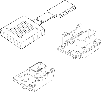
For a complete wiring diagram, refer to the Wiring Information.
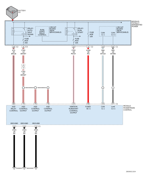 |
Possible Causes |
|---|
| FUSED B(+) CIRCUIT OPEN OR SHORTED |
| GROUND CIRCUIT OPEN |
| FUSED IGNITION SWITCH OUTPUT (RUN-START) CIRCUIT OPEN OR SHORTED |
| FUSED ASD/MAIN RELAY OUTPUT CIRCUIT OPEN OR SHORTED |
| CAN C BUS (+) CIRCUIT OPEN |
| CAN C BUS (-) CIRCUIT OPEN |
| POWERTRAIN CONTROL MODULE (PCM) |
1. TEST FOR INTERMITTENT CONDITION
| NOTE: | Check for any TSB(s) related to the condition. If a TSB applies, perform the procedure outlined in the TSB before continuing. |
| 1. | Turn the ignition on. |
| NOTE: | Make sure the Ignition Off Draw (IOD) fuse is installed and battery voltage is between 10.0 and 16.0 volts. |
| 2. | With the scan tool, read the module status. |
| NOTE: | Check the TIPM for any active CAN hardware DTCs, perform DTC before proceeding. |
Does the scan tool indicate that the module is active on the bus?
Yes
- The no response condition is not present at this time. Using the wiring diagrams as a guide, inspect the wiring for chafed, pierced, pinched, and partially broken wires and the wiring harness connectors for broken, bent, pushed out, and corroded terminals.
- Perform the BODY VERIFICATION TEST. (Refer to 28 - DTC-Based Diagnostics/MODULE, Body Control (BCM) - Standard Procedure).
No
- Go To 2
2. CHECK THE (A209) FUSED B(+) CIRCUIT FOR AN OPEN OR SHORT
| 1. | Turn the ignition off. |
| 2. | Disconnect the PCM C1 harness connector. |
Do not probe the PCM harness connectors. Probing the PCM harness
connectors will damage the PCM terminals resulting in poor terminal
to pin connection. Install the GPEC Diagnostic Adaptor to perform
the diagnosis.
CAUTION:
| 3. | Connect the Adapter, GPEC Diagnostic 10436 . |
| 4. | Using a 12-volt test light connected to ground, probe the (A209) Fused B(+) circuit at the GPEC Adaptor. |
Does the test light illuminate brightly?
Yes
- Go To 3
No
- Repair the open or short in the (A209) Fused B(+) circuit.
-
Perform the POWERTRAIN
VERIFICATION TEST. (Refer to
28 - DTC-Based Diagnostics/MODULE, Powertrain Control (PCM)
- Standard
Procedure).
3. CHECK THE (Z921) GROUND CIRCUITS FOR AN OPEN
| 1. | Turn the ignition off. |
| 2. | Using a 12 volt test light connected to 12 volts, probe each of the (Z921) Ground circuits at the GPEC Adaptor. |
| 3. | Wiggle test each circuit during the test to check for an intermittent open in the circuit. |
| NOTE: | The test light should be illuminated and bright. Compare the brightness to that of a direct connection to the battery. |
Is the test light illuminated and bright?
Yes
- Go To 4
No
- Repair the (Z921) ground circuit(s) for an open or high resistance.
- Perform the POWERTRAIN VERIFICATION TEST. (Refer to 28 - DTC-Based Diagnostics/MODULE, Powertrain Control (PCM) - Standard Procedure).
4. CHECK THE (F202) FUSED IGNITION SWITCH OUTPUT (RUN-START) CIRCUIT FOR AN OPEN OR SHORT
| 1. | Reconnect the PCM C1 harness connector with the GPEC Adaptor connected in line. |
| 2. | Turn the ignition on. |
| 3. | Using a 12 volt test light connected to ground, probe the (F202) Fused Ignition Switch Output circuit at the GPEC Adaptor. |
| 4. | Check the circuit with the ignition on, engine running position, and during cranking. |
| 5. | Wiggle test each circuit during the test to check for an intermittent open in the circuit. |
| NOTE: | The test light should be illuminated and bright. Compare the brightness to that of a direct connection to the battery. |
Is the test light illuminated and bright?
Yes
- Go To 5
No
- Repair the open or short in the (F202) Fused Ignition Switch Output (Run-Start) circuit.
-
Perform the POWERTRAIN
VERIFICATION TEST. (Refer to
28 - DTC-Based Diagnostics/MODULE, Powertrain Control (PCM)
- Standard
Procedure).
5. CHECK THE (F342) FUSED ASD RELAY OUTPUT CIRCUIT FOR AN OPEN OR SHORT
| 1. | Remove the ASD/Main Relay. |
| 2. | Connect a fused jumper wire between terminals 30 and 87. |
| 3. | Using a 12-volt test light connected to ground, check the (F342) Fused ASD Relay Output circuit at the GPEC Adaptor. |
Does the test light illuminate brightly?
Yes
- Go To 6
No
- Repair the open or short in the (F342) Fused ASD Relay Output circuit.
-
Perform the POWERTRAIN
VERIFICATION TEST. (Refer to
28 - DTC-Based Diagnostics/MODULE, Powertrain Control (PCM)
- Standard
Procedure).
6. CHECK THE (D65) CAN C BUS (+) CIRCUIT FOR AN OPEN
| 1. | Turn the ignition off. |
| 2. | Disconnect the TIPM C1 harness connector. |
| 3. | Measure the resistance of the (D65) CAN C Bus (+) circuit between the TIPM C2 harness connector and the GPEC Adaptor. |
Is the resistance below 5.0 Ohms?
Yes
- Go To 7
No
- Repair the open in the (D65) CAN C Bus (+) circuit.
- Perform the POWERTRAIN VERIFICATION TEST. (Refer to 28 - DTC-Based Diagnostics/MODULE, Powertrain Control (PCM) - Standard Procedure).
7. CHECK THE (D64) CAN C BUS (-) CIRCUIT FOR AN OPEN
| 1. | Measure the resistance of the (D64) CAN C Bus (-) circuit between the TIPM C2 harness connector and the GPEC Adaptor. |
Is the resistance below 5.0 Ohms?
Yes
- Replace and program the Powertrain Control Module (PCM) in accordance with the Service Information. (Refer to 08 - Electrical/8E - Electronic Control Modules/MODULE, Powertrain Control - Removal) .
- Perform the POWERTRAIN VERIFICATION TEST. (Refer to 28 - DTC-Based Diagnostics/MODULE, Powertrain Control (PCM) - Standard Procedure).
No
- Repair the open in the (D64) CAN C Bus (-) circuit.
- Perform the POWERTRAIN VERIFICATION TEST. (Refer to 28 - DTC-Based Diagnostics/MODULE, Powertrain Control (PCM) - Standard Procedure).