NO RESPONSE FROM TCM (TRANSMISSION CONTROL MODULE)
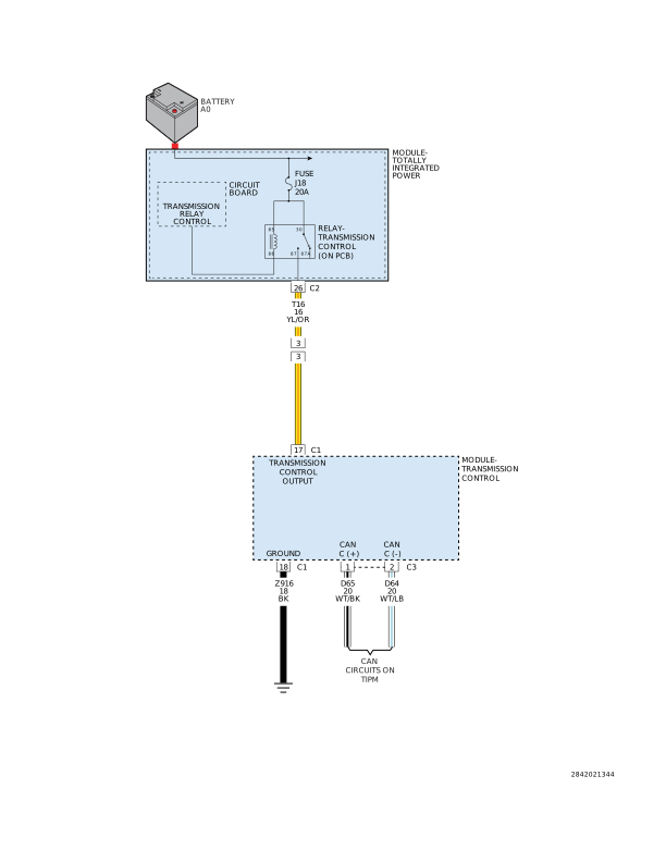
For a complete wiring diagram, refer to the Wiring
Information.
Possible Causes
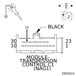
(Z916) GROUND CIRCUIT OPEN
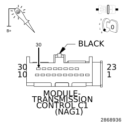
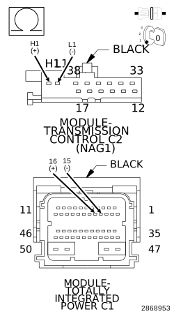
(T16) TRANSMISSION CONTROL OUTPUT CIRCUIT OPEN OR SHORTED
(D65) CAN C BUS (+) CIRCUIT OPEN
(D64) CAN C BUS (-) CIRCUIT OPEN
TRANSMISSION CONTROL MODULE (TCM)
1.
TEST FOR INTERMITTENT CONDITION
NOTE:
Check for any TSB(s) related to the condition. If a TSB applies, perform the procedure outlined in the TSB before continuing.
1.
Turn the ignition on.
NOTE:
Make sure the IOD fuse is installed and battery voltage is between 10.0 and 16.0 volts.
2.
With the scan tool, read the module status.
NOTE:
Check the TIPM for any active CAN hardware DTCs, perform DTC before proceeding.
Does the scan tool indicate that the module is active on the bus?
Yes
The no response condition is not present at this time. Using the wiring diagrams as a guide, check all related splices and connectors for signs of water intrusion, corrosion, pushed out or bent terminals, and correct pin tension.