NO RESPONSE FROM THE STEERING ANGLE SENSOR (SAS)
 |
For a complete wiring diagram, refer to the Wiring Information.
Possible Causes |
|---|
| (F943) FUSED RUN/START RELAY OUTPUT CIRCUIT OPEN OR SHORTED |
| (Z910) GROUND CIRCUIT OPEN |
| (D65) CAN C BUS (+) CIRCUIT OPEN |
| (D64) CAN C BUS (-) CIRCUIT OPEN |
| STEERING ANGLE SENSOR |
1. TEST FOR INTERMITTENT CONDITION
| NOTE: | Check for any TSB(s) related to the condition. If a TSB applies, perform the procedure outlined in the TSB before continuing. |
| 1. | Turn the ignition on. |
| NOTE: | Ensure the IOD fuse is installed and battery voltage is between 10.0 and 16.0 volts. |
| 2. | With the scan tool, select ECU View. |
| NOTE: | A red "X" will be next to the module that is not communicating, indicating that the module is not active on the Bus network. A green check indicates that the module is active on the Bus network. |
Does the scan tool display a red "X" next to the sensor?
Yes
- Go To 2
No
- The no response condition is not present at this time. Using the wiring diagram/schematic as a guide, inspect the wiring for chafed, pierced, pinched, and partially broken wires and the wiring harness connectors for broken, bent, pushed out, and corroded terminals.
2. (F943) FUSED RUN/START RELAY OUTPUT CIRCUIT OPEN OR SHORTED
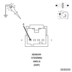 |
| 1. | Turn the ignition off. |
| 2. | Disconnect the Steering Angle Sensor harness connector. |
| 3. | Turn the ignition on. |
| 4. | Using a 12-volt test light connected to ground, check the (F943) Fused Run/Start Relay Output circuit. |
Does the test light illuminate brightly?
Yes
- Go To 3
No
- Repair the (F943) Fused Run/Start Relay Output circuit for an open or short.
-
Perform the BODY VERIFICATION TEST. (Refer to 28 - DTC-Based Diagnostics/MODULE, Totally Integrated Power (TIPM)
- Standard Procedure)
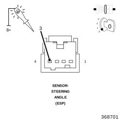 |
| 1. | Turn the ignition off. |
| 2. | Using a 12-volt test light connected to 12-volts, check the (Z910) ground circuit. |
Does the test light illuminate brightly?
Yes
- Go To 4
No
- Repair the (Z910) ground circuit for an open.
-
Perform the BODY VERIFICATION TEST. (Refer to 28 - DTC-Based Diagnostics/MODULE, Totally Integrated Power (TIPM)
- Standard Procedure)
4. (D65) CAN C BUS (+) CIRCUIT OPEN
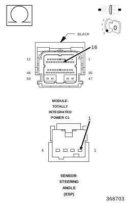 |
| 1. | Disconnect the TIPM C1 harness connector. |
| 2. | Measure the resistance of the (D65) CAN C Bus (+) circuit between the TIPM C1 harness connector and the Steering Angle Sensor connector. |
Is resistance below 5.0 ohms?
Yes
- Go To 5
No
- Repair the (D65) CAN C Bus (+) circuit for an open.
-
Perform the BODY VERIFICATION TEST. (Refer to 28 - DTC-Based Diagnostics/MODULE, Totally Integrated Power (TIPM)
- Standard Procedure)
5. (D64) CAN C BUS (-) CIRCUIT OPEN
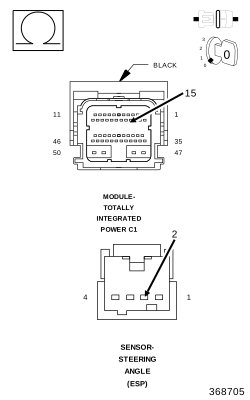 |
| 1. | Measure the resistance of the (D64) CAN C Bus (-) circuit between the TIPM C1 harness connector and the Steering Angle Sensor connector. |
Is resistance below 5.0 ohms?
Yes
- Replace the Steering Angle Sensor in accordance with the Service Information.
- Perform the BODY VERIFICATION TEST. (Refer to 28 - DTC-Based Diagnostics/MODULE, Totally Integrated Power (TIPM) - Standard Procedure)
No
- Repair the (D264) CAN C Bus (-) circuit for an open.
-
Perform the BODY VERIFICATION TEST. (Refer to 28 - DTC-Based Diagnostics/MODULE, Totally Integrated Power (TIPM)
- Standard Procedure)