Heated Systems
- DIAGNOSIS AND TESTING - ELECTRIC BACK LIGHT (EBL) SYSTEM
- DIAGNOSIS AND TESTING - HEATED SEAT ELEMENT
- DIAGNOSIS AND TESTING - HEATED SEAT SYSTEM
DIAGNOSIS AND TESTING - ELECTRIC BACK LIGHT (EBL) SYSTEM
| NOTE: |
Illumination of the defogger switch indicator lamp does not necessarily mean that electrical current is reaching the rear window glass heating grid. |
| NOTE: |
See Wiring Information for circuit descriptions and diagrams. |
Operation of the EBL system can be confirmed by the following:
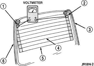 |
| NOTE: |
Typical heated rear window glass shown. |
- Use a scan tool and check for Diagnostic Trouble Codes (DTCs) related to the rear window defogger switch, Cabin Compartment Node (CCN) and the Totally Integrated Power Module (TIPM). If no DTCs are found, go to Step #2. If any DTCs are found, repair as required, then proceed to Step #2.
- Turn the ignition switch to RUN. Set the rear window defogger switch to ON. Rear window defogger operation can be checked by feeling the surfaces of the rear window glass. A distinct difference in temperature between the grid lines (5) and the adjacent clear glass should be detected within three to four minutes of operation.
-
If a temperature difference is not detected, use a 12-volt DC voltmeter and contact the rear glass heating grid terminal A (1) with the negative lead, and terminal B (2) with the positive lead. The voltmeter should read battery voltage. If the voltmeter does not read battery voltage, check the following:
- Confirm the ignition switch is in RUN.
- Confirm the rear window defogger switch is ON.
- Confirm the EBL feed wire (3) is connected to the heating grid positive terminal and that there is continuity between the TIPM and the heating grid.
- Confirm the EBL ground wire (6) is connected to the heating grid negative terminal and that there is continuity to ground.
- If broken defogger grid lines or bus bars are suspected, use a 12-volt DC voltmeter and contact terminal A with the negative lead and each rear glass heating grid line at its mid-point C (4) with the positive lead. The voltmeter should read approximately 6 volts at each grid line mid-point. If the voltmeter does not read approximately 6 volts, repair the open grid line(s) or bus bar(s) (Refer to 08 - Electrical/8G - Heated/Cooled Systems/Heated Glass/GRID, Defogger - Standard Procedure) .
-
If the EBL system operation has been verified but the rear window defogger indicator does not illuminate, replace the A/C-heater control (Refer to 24 - Heating and Air Conditioning/Controls/CONTROL, A/C and Heater - Removal)
.
DIAGNOSIS AND TESTING - HEATED SEAT ELEMENT
| NOTE: |
For complete circuit diagrams, see Wiring Information. Wiring Information includes wiring diagrams, connector pin-out and location views, details of wire harness routing and retention, splice and ground locations and proper wire and connector repair procedures. |
| NOTE: |
The wire harness connectors for the heating elements are located under the seat. |
| NOTE: |
When testing the heated seat elements for resistance, be certain to sit in the seat in question and move around the heating elements within the seat while testing. Moving the heating elements will help eliminate the possibility of an intermittent open in the element, which would only be evident in a certain position. |
- Locate and disconnect the seat electrical connectors as necessary.
- Check the resistance between the circuits leading in and out of the suspect heated seat element. The resistance should be between the specifications listed in the following Heated Seat Element Resistance chart. If OK, (Refer to 08 - Electrical/8G - Heated/Cooled Systems/Heated Seats - Diagnosis and Testing) . If not OK, replace the inoperative heated seat element (Refer to 08 - Electrical/8G - Heated/Cooled Systems/Heated Seats/PAD, Heater - Removal) .
HEATED SEAT ELEMENT RESISTANCE
|
Element Location |
Acceptable Resistance Value |
|---|---|
|
Seat Bottom Cushion |
6.36 - 2.97 ohms |
|
Seat Back Cushion |
6.36 - 2.97 ohms |
DIAGNOSIS AND TESTING - HEATED SEAT SYSTEM
| NOTE: |
Vehicles equipped with the heated seat option utilize a low voltage cut-off feature. This feature turns off power to the heated seat system anytime vehicle voltage is below 11.7 volts or above 15.5 volts. Be certain to check the vehicle electrical system for proper voltage anytime the heated seat system appears inoperative. |
| NOTE: |
If a Diagnostic Trouble Code (DTC) can not be verified, it is a good indication that an intermittent fault condition may be present. To help find an intermittent problem, sit in the seat in question and move around the heating elements within the seat while testing continuity. Wiggle the heated seat wire harness and electrical connectors while testing continuity. |
| NOTE: |
For complete circuit diagrams, see Wiring Information. Wiring Information includes wiring diagrams, connector pin-out and location views, details of wire harness routing and retention, splice and ground locations and proper wire and connector repair procedures. |
Before testing any individual components in the heated seat system, check the following:
- Check the vehicles battery open-circuit voltage and charging system performance. If the vehicle's electrical system is defective or weak it may not be suppling sufficient energy to operate the heated seat system.
- Using a scan tool, check for any Diagnostic Trouble Codes (DTCs) related to the Cabin Compartment Node (CCN), Heated Seat Module (HSM) and heated seat switches. If any DTCs are found, repair as necessary (Refer to 28 - DTC-Based Diagnostics/NODE, Cabin Compartment (CCN) - Diagnosis and Testing).
- If there are no DTCs and the front heated seat system functions properly, but one or both of the Light Emitting Diode (LED) indicators in a front heated seat switch do not illuminate, replace the accessory switch pod (Refer to 08 - Electrical/8J - Instrument Cluster/POD, Switch - Removal) .