MODULE, Anti-Lock Brake System
DESCRIPTION
The Antilock Brake Module (ABM) is mounted to the Hydraulic Control Unit (HCU) and operates the ABS system.
OPERATION
The ABM voltage source is through the ignition switch in the RUN position. The ABM contains dual microprocessors. A logic block in each microprocessor receives identical sensor signals. These signals are processed and compared simultaneously. The ABM contains a self check program that illuminates the ABS warning light when a system fault is detected. Faults are stored in a diagnostic program memory and are accessible with the scan tool. ABS faults remain in memory until cleared, or until after the vehicle is started approximately 50 times. Stored faults are not erased if the battery is disconnected.
REMOVAL
 |
- Remove the master cylinder (Refer to 05 - Brakes/Hydraulic/Mechanical/MASTER CYLINDER, Brake - Removal) .
- Install prop rod on the brake pedal to keep pressure on the brake system.
- Remove negative battery cable from the battery.
-
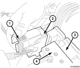
Pull up on the ABM harness connector release (1) and remove connector (2).
-
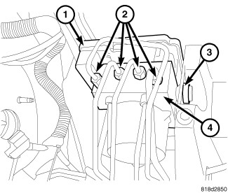
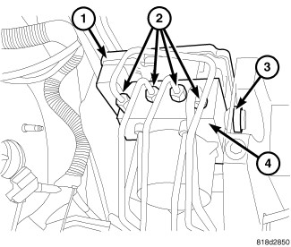
Remove brake lines (2) from the HCU (4).
-
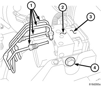
Remove HCU/ABM mounting nuts and bolt (4) and remove HCU (2) / ABM (3) as an assembly.
CAUTION: When removing ABM from HCU, be sure to completely separate the two components (approximately 38 mm (1.5 in.) before removing ABM. Otherwise, damage to the pressure sensor or Pump Motor connection may result requiring HCU replacement. Do not to touch the sensor terminals on the HCU side or the contact pads on the ABM side as this may result in contamination and issues in the future.
-
Remove the ABM from the HCU.
INSTALLATION
 |
When removing ABM from HCU, be
sure to completely separate the two components (approximately 38 mm
(1.5 in.) before removing ABM. Otherwise, damage to the pressure sensor
or Pump Motor connection may result requiring HCU replacement. Do
not to touch the sensor terminals on the HCU side or the contact pads
on the ABM side as this may result in contamination and issues in
the future.
CAUTION:
| NOTE: |
If the ABM is being replaced with a new ABM is must be reprogrammed with the use of a scan tool. |
- Install the ABM on the HCU and tighten then screws to 2 N·m (16 in. lbs.).
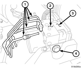
- Install HCU/ABM (2AND3) on the mounting studs (4).
-
Install mounting nuts and bolt (4). Tighten to 11.5 N·m (102 in. lbs.).
-
Install brake lines (2) to the HCU (4) and tighten to 19 N·m (170 in. lbs.).
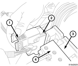
- Install wiring harness connector (2) to the ABM and push down on the release (1) to secure the connector.
- Install the master cylinder (Refer to 05 - Brakes/Hydraulic/Mechanical/MASTER CYLINDER, Brake - Installation) .
- Install negative battery cable to the battery.
-
Bleed ABS brake system (Refer to 05 - Brakes - Standard Procedure)
.