SENSOR, Intrusion Module
DESCRIPTION
Intrusion sensor microwave transducers are part of the premium version of the Vehicle Theft Alarm (VTA) in the Vehicle Theft Security System (VTSS). The premium version of the VTA is only available in vehicles built for certain markets, where the additional features offered by this system are required. There are two (two-door vehicles) or three (four-door vehicles) sensors used in each vehicle. These units are designed to provide interior motion detection inputs to the intrusion module, which serves as the interface between the Front Control Module (FCM), the ElectroMechanical Instrument Cluster (EMIC) (also known as the Cab Compartment Node/CCN) and the alarm siren.
The sensors are each located within the passenger compartment of the vehicle, concealed behind the interior trim components. A sensor located in the lower center stack of the instrument panel monitors the front seating area of the vehicle. This sensor is concealed behind a lower center trim panel below the instrument panel switch pod. A second sensor is located within the swing gate and monitors the cargo area of all vehicles as well as the second row seating area of two-door vehicles. This sensor is concealed behind a molded plastic grille near the left end of the swing gate inner panel.
A third sensor is used only on four-door vehicles. This sensor is located within the center floor console to monitor the second row seating area of four-door vehicles. This sensor is concealed behind the rear trim cover of the console on the back of the console bin.
Concealed within the molded plastic sensor housing is the circuitry of the sensor which includes the microwave send and receive transducer. The housings each include integral mounting provisions dedicated to the intended sensor mounting location. Each sensor is connected through either an integral connector receptacle or an integral pigtail wire to the vehicle electrical system.
An intrusion sensor microwave transducer cannot be adjusted or repaired and, if ineffective or damaged, it must be replaced.
OPERATION
The intrusion sensor microwave transducers operate only when they are energized by the intrusion module. The sensors transmit microwave signals throughout the vehicle cabin through a transducer. The sensor then listens to the returned microwave signals as they bounce off of objects in the vehicle interior and provide input signals to the intrusion module. If an object is moving in the interior, a detection circuit in the intrusion module senses this movement through the modulation of the returning signals that occur due to the Doppler effect. The intrusion module monitors the current draw of the sensor circuits to determine the condition of the sensors and, if the draw is too high or too low, it will store a Diagnostic Trouble Code (DTC) for any fault that is detected.
The hard wired circuits for the intrusion sensor microwave transducers may be diagnosed using conventional diagnostic tools and procedures. Refer to the appropriate wiring information. However, conventional diagnostic methods will not prove conclusive in the diagnosis of the intrusion sensors or the electronic controls and communication between other modules and devices that provide some features of the VTA system. The most reliable, efficient and accurate means to diagnose the intrusion sensor or the electronic controls and communication related to intrusion sensor operation requires the use of a diagnostic scan tool. Refer to the appropriate diagnostic information.
CONSOLE
| NOTE: |
An intrusion sensor is installed within the center floor console only on four-door vehicles equipped with the export premium version of the Vehicle Theft Alarm (VTA). |
- Disconnect and isolate the negative cable from the battery.
- Remove the center console from the vehicle. (Refer to 23 - Body/Interior/CONSOLE, Center - Removal) .
- Place the center console on a suitable work surface. Be certain to take the proper precautions to protect the console from receiving cosmetic damage during the service procedure.
- Remove the screws at each rear side of the console that secure the rear trim cover to the console.
- Remove the rear trim cover from the console.
- Remove the fasteners securing the intrusion sensor to the rear outer surface of the center console bin.
- Remove the intrusion sensor from the center console bin.
INSTRUMENT PANEL
To avoid serious or fatal injury
on vehicles equipped with airbags, disable the Supplemental Restraint
System (SRS) before attempting any steering wheel, steering column,
airbag, seat belt tensioner, impact sensor or instrument panel component
diagnosis or service. Disconnect and isolate the battery negative
(ground) cable, then wait two minutes for the system capacitor to
discharge before performing further diagnosis or service. This is
the only sure way to disable the SRS. Failure to take the proper precautions
could result in accidental airbag deployment.
WARNING:
| NOTE: |
An intrusion sensor is installed within the instrument panel only on vehicles equipped with the export premium version of the Vehicle Theft Alarm (VTA). |
 |
- Disconnect and isolate the negative cable from the battery.
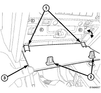
- Using a trim stick or another suitable wide flat-bladed tool, gently and evenly pry the upper edges of the lower center trim panel (3) away from the instrument panel far enough to disengage the two snap clips (2) that secure the top of the panel to the base trim of the instrument panel center stack.
- Rotate the lower center trim panel downward far enough to disengage the two tabs (1) at the bottom of the panel from the base trim of the instrument panel center stack.
- Disconnect the intrusion sensor pigtail wire from the instrument panel wire harness.
- Remove the fasteners securing the intrusion sensor to the base trim of the instrument panel center stack.
-
Remove the intrusion
sensor from the instrument panel.
SWING GATE
| NOTE: |
An intrusion sensor is installed within the swing gate only on vehicles equipped with the export premium version of the Vehicle Theft Alarm (VTA). |
- Disconnect and isolate the negative cable from the battery.
- Unlatch and open the swing gate.
- Unsnap the inboard side of the louvered plastic access panel and unhook it from the outboard edge of the access hole on the inside of the swing gate near the latch.
- Reach through the access hole to disconnect the intrusion sensor pigtail connector from the swing gate wire harness connector.
- Remove the fasteners securing the intrusion sensor to the inside of the swing gate.
- Remove the intrusion sensor from the swing gate.
CONSOLE
| NOTE: |
An intrusion sensor is installed within the center floor console only on four-door vehicles equipped with the export premium version of the Vehicle Theft Alarm (VTA). |
- Position the intrusion sensor to the rear outer surface of the center console bin.
- Install the fasteners that secure the intrusion sensor to the center console bin.
- Position the rear trim cover to the console.
- Install and tighten the screws at each rear side of the console that secure the rear trim cover to the console. Tighten the screws to 2 N·m (18 in. lbs.).
- Reinstall the center console into the vehicle. (Refer to 23 - Body/Interior/CONSOLE, Center - Installation) .
- Reconnect the negative cable to the battery.
INSTRUMENT PANEL
To avoid serious or fatal injury
on vehicles equipped with airbags, disable the Supplemental Restraint
System (SRS) before attempting any steering wheel, steering column,
airbag, seat belt tensioner, impact sensor or instrument panel component
diagnosis or service. Disconnect and isolate the battery negative
(ground) cable, then wait two minutes for the system capacitor to
discharge before performing further diagnosis or service. This is
the only sure way to disable the SRS. Failure to take the proper precautions
could result in accidental airbag deployment.
WARNING:
| NOTE: |
An intrusion sensor is installed within the instrument panel only on vehicles equipped with the export premium version of the Vehicle Theft Alarm (VTA). |
|
- Position the intrusion sensor to the base trim of the instrument panel center stack.
- Install the fasteners that secure the intrusion sensor to the instrument panel.
- Reconnect the intrusion sensor pigtail wire to the instrument panel wire harness.
- Engage the two tabs (1) at the bottom of the lower center trim panel (3) into the receptacles in the base trim of the instrument panel center stack and roll the top of the panel upward.
- Using hand pressure, press firmly and evenly on the trim panel over each of the two snap clips (2) until they snap into their receptacles in the instrument panel.
-
Reconnect the negative
cable to the battery.
SWING GATE
| NOTE: |
An intrusion sensor is installed within the swing gate only on vehicles equipped with the export premium version of the Vehicle Theft Alarm (VTA). |
- Reach through the access hole on the inside of the swing gate near the latch to position the intrusion sensor to the inside of the swing gate.
- Install the fasteners that secure the intrusion sensor to the swing gate.
- Reconnect the intrusion sensor pigtail connector to the swing gate wire harness connector.
- Reinstall the louvered plastic access panel over the access hole by hooking it into the outboard edge of the hole, then pressing firmly and evenly over the two snap clip locations on the inboard side of the panel until it snaps into place.
- Reconnect the negative cable to the battery.