MODULE, Hands Free (HFM)
DESCRIPTION
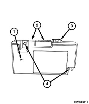 |
The Hands Free Module (HFM) (1) (also known as the Bluetooth™ module) is found in vehicles equipped with the optional Uconnect® Hands Free Phone System. This module is located on a bracket of the instrument panel support structure behind the instrument panel center bezel. The HFM hardware and circuitry is contained and protected within a molded black plastic housing that has two integral mounts (4). The HFM is secured to the bracket by two screws.
The HFM has three integral connector receptacles that are oriented toward the dash panel when it is installed in the vehicle. The two largest receptacles (2) connect the HFM to the vehicle electrical system through dedicated take outs and connectors of the instrument panel wire harness. The smallest connector (3) accepts a Universal Serial Bus (USB) cable connector that connects the HFM to the Radio Receiver Module (RRM) (also known as the radio or the head unit).
The internal circuitry of the HFM includes a microcontroller, flash memory and a Bluetooth™ module. The module also includes sophisticated Voice Recognition (VR) software. The HFM software is flash programmable.
The HFM cannot be adjusted or repaired and, if damaged or ineffective,
the entire HFM must be replaced.
OPERATION
The Hands Free Module (HFM) (also known as the Bluetooth™ module) is used only in vehicles equipped with the optional Uconnect™ Hands Free Phone System. The HFM contains the microcontroller, logic and memory circuits of the Hands Free Phone System. The HFM uses On-Board Diagnostics (OBD) and can communicate with other electronic modules in the vehicle as well as with the diagnostic scan tool using the Controller Area Network data bus. This method of communication is also used for Hands Free Phone System diagnosis and testing through the 16-way data link connector located on the driver side lower edge of the instrument panel and is used by the HFM to acquire vehicle configuration data.
The HFM brings together several technologies in the vehicle. The HFM uses Bluetooth® technology to provide wireless connectivity between a paired compatible personal cellular telephone or a paired personal wireless audio streaming device and other on board vehicle systems. The HFM also uses sophisticated Voice Recognition (VR) software to recognize and respond appropriately to certain verbal commands, which allows hands free control of a number of optional vehicle systems and features. In addition to English, the VR software includes Spanish and French language capability. Incoming call voices are broadcast through the front audio system speakers of the vehicle, automatically overriding any other audio signals on the front speakers while the Hands Free Phone is in use.
The HFM circuitry receives battery current through a fused ignition output (unlock - run - start) circuit and fuse through the Totally Integrated Power Module (TIPM). The HFM also has a path to ground at all times received through a ground circuit and take out of the instrument panel wire harness that is secured to the body sheet metal. These connections allow the HFM to operate whenever the status of the ignition switch is Unlock, Run or Start. Other inputs to the HFM include:
- Cellular Telephone - Using the Bluetooth® wireless standard, the Bluetooth® transceiver within the HFM can pair and prioritize up to 10 combined personal cellular telephones and Bluetooth® capable portable media devices, each of which is given a spoken identification by the user during the setup process. The phone connectivity enables wireless calling, text messaging and cellular phone contact list synchronization features. The HFM will communicate with a paired device that is anywhere within the vehicle. However, placing metal between the HFM and the device may result in unwanted shielding of the signals.
- Electronic Vehicle Information Center Switch Pod - Vehicles equipped with the Uconnect™ Hands Free Phone System feature have two push buttons added to the Electronic Vehicle Information Center (EVIC) switch pod located in the left horizontal spoke of the steering wheel. One push button is labeled VR (Voice Recognition) and initiates the Uconnect™ Voice Command feature. The second button is identified by a telephone hand set icon and initiates the Uconnect™ Hands Free Phone feature. The HFM monitors electronic messages received over the CAN data bus from the Steering Control Module (SCM) indicating the status of each of these two switches.
- Radio Receiver Module Switches - Vehicles equipped with the Uconnect™ Hands Free Phone System feature two push buttons available within the Radio Receiver Module (RRM) (also known as the radio or the head unit) located in the instrument panel center bezel above the instrument panel center stack. One push button is labeled VR (Voice Recognition) and activates the Uconnect™ Voice Command feature. The second button is identified by a telephone hand set icon and activates the Uconnect™ Hands Free Phone feature. The HFM monitors electronic messages received over the CAN data bus from the RRM indicating the status of each of these two switches.
- Streaming Audio - BlueTooth® Streaming Audio (BTSA) allows audio content from any paired personal Bluetooth™ capable portable media device or from an internet radio application on a Bluetooth™ capable smart phone to be accessed and listened to through the audio system of the vehicle.
- Universal Serial Bus - For music stored on a Universal Serial Bus (USB) flash drive, the HFM receives metadata such as artist names and song titles from the RRM over a dedicated USB connection. This allows the audio content of these connected devices to be searched for and accessed using the Uconnect™ Voice Command feature.
- Verbal Commands - Two wired microphones integral to the inside rear view mirror provide verbal commands from the vehicle operator to both the HFM and the RRM, which enables the control of several vehicle systems and features using the Uconnect™ Voice Command feature through the Voice Recognition (VR) software.
Outputs of the HFM include:
- Analog Audio Outputs - The HFM has both left and right channel analog audio output circuits. The HFM provides Uconnect™ Hands Free call audio, Bluetooth Streaming Audio® (BTSA) and Hands Free voice prompt audio to the RRM through these circuits.
- Digital Electronic Messages - The VR software within the HFM is programmed to convert Uconnect™ Voice Command verbal inputs into the appropriate electronic request message, which is then transmitted by the HFM over the CAN data bus. When the Electronic Control Unit (ECU) that controls the requested feature receives the electronic request message over the CAN data bus, it will invoke the requested action.
- Wireless Messages - The VR software within the HFM is also programmed to convert Uconnect™ Voice Command verbal inputs into the appropriate Bluetooth™ wireless request message, which is then transmitted by the Bluetooth® transceiver to the appropriate paired wireless device to invoke the requested action.
The HFM uses On-Board Diagnostics (OBD) to monitor all of the systems and circuits it controls, then sets active and stored Diagnostic Trouble Codes (DTC) for any monitored system faults it detects. The HFM will also send electronic message requests to the ElectroMechanical Instrument Cluster (EMIC) (also known as the Cab Compartment Node/CCN) for the display of certain textual warning messages related to some detected system conditions or faults.
The hard wired circuits of the HFM may be diagnosed using conventional diagnostic tools and procedures. Refer to the appropriate wiring information. The wiring information includes wiring diagrams, proper wire and connector repair procedures, details of wire harness routing and retention, connector pin out information and location views for the various wire harness connectors, splices and grounds.
However, conventional diagnostic methods will not prove conclusive in the diagnosis of the HFM or the electronic controls and communication between modules and other devices that provide some features of the Uconnect™ Hands Free Phone system. The most reliable, efficient and accurate means to diagnose the HFM or the electronic controls and communication related to Uconnect™ Hands Free Phone system operation requires the use of a diagnostic scan tool. Refer to the appropriate diagnostic information.
DIAGNOSIS AND TESTING - HANDS FREE MODULE
The hard wired circuits of the Hands Free Module (HFM) (also known as the Bluetooth™ module) may be diagnosed using conventional diagnostic tools and procedures. Refer to the appropriate wiring information. The wiring information includes wiring diagrams, proper wire and connector repair procedures, details of wire harness routing and retention, connector pin out information and location views for the various wire harness connectors, splices and grounds.
However, conventional diagnostic methods will not prove conclusive in the diagnosis of the HFM or the electronic controls and communication between modules and other devices that provide some features of the Uconnect™ Hands Free Phone system. The most reliable, efficient and accurate means to diagnose the HFM or the electronic controls and communication related to Uconnect™ Hands Free Phone system operation requires the use of a diagnostic scan tool. Refer to the appropriate diagnostic information.
REMOVAL
To avoid serious or fatal injury
on vehicles equipped with airbags, disable the Supplemental Restraint
System (SRS) before attempting any steering wheel, steering column,
airbag, seat belt tensioner, impact sensor or instrument panel component
diagnosis or service. Disconnect and isolate the battery negative
(ground) cable, then wait two minutes for the system capacitor to
discharge before performing further diagnosis or service. This is
the only sure way to disable the SRS. Failure to take the proper precautions
could result in accidental airbag deployment.
WARNING:
 |
- Disconnect and isolate the negative cable from the battery.
-
Remove the center bezel
(1) from the instrument panel. (Refer to 23 - Body/Instrument Panel/BEZEL, Instrument Panel - Removal)
.
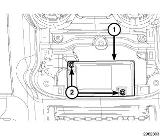
- Remove the two screws (2) that secure the Hands Free Module (HFM) (1) to the instrument panel support structure.
- Pull the HFM away from the instrument panel far enough to access and disconnect the instrument panel wire harness connectors from the HFM connector receptacles.
-
Remove the HFM (1)
from the vehicle.
INSTALLATION
To avoid serious or fatal injury
on vehicles equipped with airbags, disable the Supplemental Restraint
System (SRS) before attempting any steering wheel, steering column,
airbag, seat belt tensioner, impact sensor or instrument panel component
diagnosis or service. Disconnect and isolate the battery negative
(ground) cable, then wait two minutes for the system capacitor to
discharge before performing further diagnosis or service. This is
the only sure way to disable the SRS. Failure to take the proper precautions
could result in accidental airbag deployment.
WARNING:
|
- Position the Hands Free Module (HFM) (1) close enough to the instrument panel to access and reconnect the instrument panel wire harness connectors to the HFM connector receptacles.
- Position the HFM to the instrument panel support structure.
-
Install and tighten
the two screws (2) that secure the HFM to the instrument panel support
structure. Tighten the screws securely.
- Reinstall the center bezel (1) onto the instrument panel. (Refer to 23 - Body/Instrument Panel/BEZEL, Instrument Panel - Installation) .
-
Reconnect the negative
cable to the battery.