SENSOR, Sun
DESCRIPTION
| NOTE: |
Typical sun sensor assembly shown. |
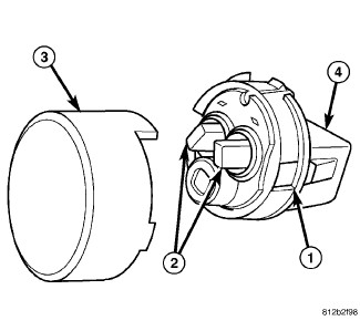 |
The Automatic Temperature Control (ATC) heating-A/C system uses
a sun sensor (1) to measure sun light intensity. The sun sensor incorporates
three sun load sensors (2) within a molded plastic case which is mounted
to the instrument panel and a clear lens (3) that protrudes through
the defroster grille. The wire harness receptacle (4) connects the
sun sensor to the vehicle electrical system.
OPERATION
The ATC heating-A/C system uses two sun sensors to balance the system in response to side-to-side variations in sun light intensity. Passengers in sun and shadow require different functional settings because they experience very different temperatures. The sun sensor assembly provides data to the A/C heater control to help determine proper mode and blend-air door positions and blower motor speeds. The sun sensors are not thermistor type sensors, but rather photo diodes. For this reason the sun sensors responds to sun light intensity rather than temperature. The sun sensor assembly is also used to sense day and night conditions for automatic headlight control, when equipped.
The sun sensor is diagnosed using a scan tool (Refer to 28 - DTC-Based Diagnostics/HVAC - Diagnosis and Testing) .
The sun sensor assembly cannot be adjusted or repaired and must be replaced if inoperative or damaged.
DIAGNOSIS AND TESTING - SUN SENSOR
Disable the airbag system before attempting any steering wheel, steering column, or instrument panel component diagnosis or service. Disconnect and isolate the negative battery (ground) cable. Wait two minutes for the airbag system capacitor to discharge before performing further diagnosis or service. This is the only sure way to disable the airbag system. Failure to follow these instructions may result in possible serious or fatal injury.
WARNING:
The sun sensor is located so that the sun rays will hit the sensors in the same way that it will hit the driver and the passenger. If the vehicle exhibits a lack of passenger comfort in sunny weather such as in the early afternoon, inspect the area around the sun sensor on top of the dash panel. It is important that the area of the sun sensor be unobstructed from plain view. Check for the following:
- Sun sensor is properly installed (Refer to 24 - Heating and Air Conditioning/Controls/SENSOR, Sun - Installation) .
- Any stickers on the windshield are not directly in front of the sun sensor.
- Any items laying on top of the instrument panel are not covering the sun sensor.
- Windshield wipers are properly adjusted.
The A/C-heater control continually monitors the sun sensor circuits and will store Diagnostic Trouble Codes (DTCs) for any problem it detects. The sun sensor can be tested in the vehicle with a scan tool (Refer to 28 - DTC-Based Diagnostics/HVAC - Diagnosis and Testing) .
REMOVAL
Disable the airbag system before attempting any steering wheel, steering column, or instrument panel component diagnosis or service. Disconnect and isolate the negative battery (ground) cable. Wait two minutes for the airbag system capacitor to discharge before performing further diagnosis or service. This is the only sure way to disable the airbag system. Failure to follow these instructions may result in possible serious or fatal injury.
WARNING:
 |
- Disconnect and isolate the negative battery cable.
-
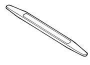
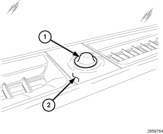
Using Trim Stick C-4755 or equivalent, remove the sun sensor (1) from the defroster grille (2).
-
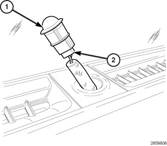
Disconnect the wire harness connector (2) from the sun sensor (1) and remove the sensor.
INSTALLATION
|
-
Position the sun sensor (1) to the top of the instrument panel and connect the wire harness connector (2) to the sensor.
- Align the tab on the sun sensor (1) with the slot in the opening in the defroster grille (2) and install the sensor onto the grille. Make sure that the sensor is fully engaged to the defroster grille.
-
Reconnect the negative battery cable.