2014 Jeep Wrangler JK Factory Service Manual 07 - Cooling

COOLER, EGR

REMOVAL


  1. Disconnect the negative battery cable.

  2.  
  3. Center and lock the steering wheel.

  4.  
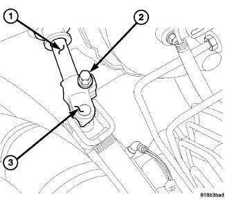
  5. Remove the pinch bolt (2) at the upper intermediate shaft (1).

  6.  
  7. Separate the upper coupler on the lower shaft (3) from the upper intermediate shaft (1) and position aside.

  8.  
  9. Remove four nuts and the engine cover.

  10.  
  11. Raise and support the vehicle (Refer to 04 - Vehicle Quick Reference/Hoisting - Standard Procedure) .

  12.  
  13. Remove the front lower splash shield.

  14.  
  15. Drain the engine coolant (Refer to 07 - Cooling - Standard Procedure) .

  16.  
  17. Remove the left wheel house splash shield (Refer to 23 - Body/Exterior/SHIELD, Splash - Removal) .

  18.  
  19. Disconnect the IAT/BPS sensor harness connector.

  20.  
  21. Disconnect the Charge Air Cooler (CAC) outlet hose from the EGR air flow control valve.

  22.  
  23. Remove the air cleaner body (Refer to 09 - Engine/Air Intake System/BODY, Air Cleaner - Removal) .

  24.  
  25. Remove generator (Refer to 08 - Electrical/8F - Engine Systems/Charging/GENERATOR - Removal) .

  26.  
  27. Remove the A/C compressor (Refer to 24 - Heating and Air Conditioning/Plumbing/COMPRESSOR, A/C - Removal) .

  28.  
  29. Remove the EGR tube (Refer to 25 - Emissions Control/Exhaust Gas Recirculation/TUBE, Exhaust Gas Recirculation (EGR) - Removal).

  30.  
  31. Disconnect the EGR valve harness connector.

  32.  
  33. Remove the lower intermediate shaft-to-upper intermediate shaft pinch bolt and disconnect the intermediate shaft.

  34.  
  35. Remove the upper radiator hose to thermostat housing.

  36.  
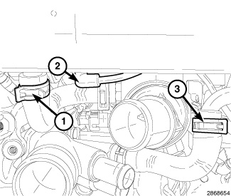
  37. Remove the two lower coolant hoses (1 and 3) from EGR cooler.

  38.  
  39. Disconnect the heater hose at the water pump inlet tube.

  40.  
  41. Disconnect the heater hose at the thermostat housing.

  42.  
  43. Disconnect the EGR bypass vacuum line (2) from vacuum solenoid.


  44.  
  45. Remove the lower EGR cooler support bracket bolt.


  46.  
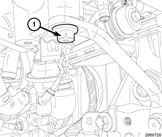
  47. Remove the two lower EGR manifold bolts (1).


  48.  
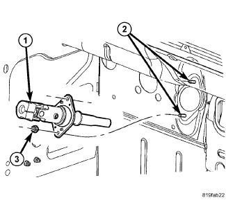
  49. Remove the two nuts (3) securing the upper intermediate shaft to the cowl and remove the shaft (1) from the studs (2).


  50.  
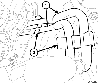
  51. Disconnect the heater tubes (1) from clips (2) and position the aside.


  52.  
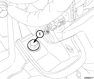
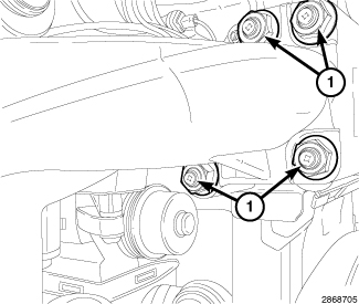
  53. Remove the left side EGR cooler support bracket bolt (1).


  54.  
  55. Remove the two upper EGR manifold bolts (1).


  56.  
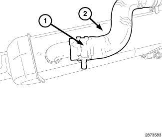
  57. Disconnect the upper coolant hose (1) from EGR cooler (2).

  58.  
  59. Remove bolts and separate the EGR cooler from manifold.

  60.  

INSTALLATION


  1. Clean the gasket mating surfaces.

  2.  
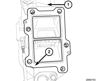
  3. Position a new gasket (2) onto the EGR cooler manifold (1).


  4.  
  5. Install the EGR cooler. Tighten bolts to 15 N·m (133 in lbs.).

  6.  
  7. Connect the upper coolant hose (1) from EGR cooler (2).


  8.  
  9. Install the EGR cooler and manifold assembly and tighten the upper bolts (1) finger tight.


  10.  
  11. Install the left side EGR cooler support bracket bolt and tighten to 25 N·m (18 ft. lbs.).


  12.  
  13. Position the heater tubes (1) back into clips (2).


  14.  
  15. Install the intermediate shaft (1) to studs (2) at cowl. Tighten nuts (3) to 13 N·m (115 in. lbs.).


  16.  
  17. Install the two lower EGR manifold bolts (1). Tighten the four bolts (1) to 25 N·m (18 ft. lbs.).


  18.  
  19. Install the lower EGR cooler support bracket bolt (1). Tighten bolt (1) to 45 N·m (33 ft. lbs.).


  20.  
  21. Connect the EGR bypass vacuum line (2) to vacuum solenoid.

  22.  
  23. Connect the heater hose at the thermostat housing.

  24.  
  25. Connect the heater hose at the water pump inlet tube.

  26.  
  27. Install the two lower coolant hoses (1 and 3) to EGR cooler.

  28.  
  29. Install the upper radiator hose to thermostat housing.

  30.  
  31. Connect the upper intermediate shaft-to-lower intermediate shaft. Tighten pinch bolt to 49 N·m (36 ft. lbs.).

  32.  
  33. Connect the EGR valve harness connector.

  34.  
  35. Install the EGR tube (Refer to 25 - Emissions Control/Exhaust Gas Recirculation/TUBE, Exhaust Gas Recirculation (EGR) - Installation).

  36.  
  37. Install the A/C Compressor. Tighten the bolts to 28 N·m (21 ft. lbs.).

  38.  
  39. Install the generator (Refer to 08 - Electrical/8F - Engine Systems/Charging/GENERATOR - Installation) .

  40.  
  41. Install the air cleaner body (Refer to 09 - Engine/Air Intake System/BODY, Air Cleaner - Installation) .

  42.  
  43. Connect the Charge Air Cooler (CAC) outlet hose to the EGR air flow control valve.

  44.  
  45. Install the left wheel house splash shield (Refer to 23 - Body/Exterior/SHIELD, Splash - Installation) .

  46.  
  47. Evacuate and charge the A/C system (Refer to 24 - Heating and Air Conditioning/Plumbing - Standard Procedure) .

  48.  
  49. Fill the cooling system (Refer to 07 - Cooling - Standard Procedure) .

  50.  
  51. Install the front lower splash shield.

  52.  
  53. Install the engine cover and securely tighten nuts.

  54.  
  55. Install the lower intermediate shaft coupler (3) to upper intermediate shaft (1).

  56.  
  57. Install the pinch bolt (2). Tighten to 49 N·m (36 ft. lbs.).

  58.  
  59. Remove the steering wheel lock.

  60.  
  61. Connect the negative battery cable.
  62.