SWITCH, Heated Seat
DESCRIPTION
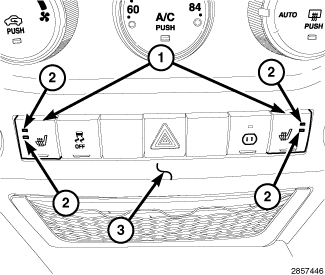 |
The front heated seat switches (1) are momentary contact push button type switches that are mounted in accessory switch pod, located in the center of the instrument panel (3). These switches allow the driver and front seat passenger to select from two different levels of electrical seat heating (high and low). Amber Light Emitting Diodes (LEDS) (2) in each switch indicate the level of heat in use: Two LEDs illuminate for high, one for low, and none for off. Pressing a heated seat switch once will select high-level heating. Pressing the same switch a second time will select low-level heating. Pressing the switch a third time will shut off the heating elements in the seat.
OPERATION
The two front heated seat switches are momentary, push button-type switches, that provide a request signal to the Heated Seat Module (HSM), over the Controller Area Network (CAN) bus, signaling the HSM to energize the heating elements for the selected seat. Light Emitting Diodes (LED) in each switch indicate the level of heat in use. The front seat switch LEDs are controlled by the HSM.
The front heated seat switches are diagnosed using a scan tool (Refer to 28 - DTC-Based Diagnostics/NODE, Cabin Compartment (CCN) - Diagnosis and Testing).
The front heated seat switches cannot be adjusted or repaired and if a switch or its LEDs are damaged or inoperative, the entire accessory switch pod must be replaced (Refer to 08 - Electrical/8J - Instrument Cluster/POD, Switch - Removal) .
REMOVAL
Disable the airbag system before
attempting any steering wheel, steering column or instrument panel
component diagnosis or service. Disconnect and isolate the negative
battery (ground) cable and wait two minutes for the airbag system
capacitor to discharge before performing further diagnosis or service.
This is the only sure way to disable the airbag system. Failure to
follow these instructions may result in accidental airbag deployment
and possible serious or fatal injury.
WARNING:
| NOTE: |
Take the proper precautions to protect the face of the center bezel from cosmetic damage while performing this procedure. |
 |
- Disconnect and isolate the negative battery cable.
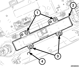
- Remove the instrument panel center bezel (4) and place it on a workbench (Refer to 23 - Body/Instrument Panel/BEZEL, Instrument Panel - Removal) .
-
Remove the four screws (1 and 3) that secure the accessory switch pod (2) to the center bezel and remove the switch pod.
INSTALLATION
| NOTE: |
Take the proper precautions to protect the face of the center bezel from cosmetic damage while performing this procedure. |
|
- Position the accesssory switch pod (2) onto the back of the instrument panel center bezel (4).
- Install the four screws (1 and 3) that secure the A/C-heater control to the center bezel. Tighten the screws to 2.2 N·m (20 in. lbs.).
- Install the instrument panel center bezel (Refer to 23 - Body/Instrument Panel/BEZEL, Instrument Panel - Installation) .
- Reconnect the negative battery cable.
-
Verify proper heated seat system operation.