SWITCH, Parking Brake
DESCRIPTION
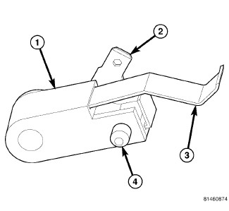 |
The park brake switch (1) is located on the park brake lever mechanism on the floor panel transmission tunnel below the center floor console. This switch includes a spade-type output terminal (2) that connects the switch to the vehicle electrical system through a dedicated take out and connector of the instrument panel wire harness. The output terminal is integral to the stationary contact within a molded plastic insulator. A locating tab (4) on the insulator engages a slot in the park brake lever mechanism for positive switch location. External to the insulator is a movable leaf contact (3) with an integral grounding lug on one end and an integral actuating lever and follower on the opposite end. The switch is secured to and grounded by a single screw to the park brake lever mechanism.
The park brake switch cannot be adjusted or repaired and, if ineffective or damaged, it must be replaced.
OPERATION
The park brake switch is a normally closed, mechanically actuated leaf contact switch that is operated by the park brake lever mechanism. The switch is grounded through its mounting to the park brake lever mechanism and provides a ground input to the ElectroMechanical Instrument Cluster (EMIC) (also known as the Cab Compartment Node/CCN) on a park brake switch sense circuit whenever the park brake is applied, and opens this circuit whenever the park brake is released. The park brake switch sense input to the EMIC is used for control of the brake indicator and may also be used as a logic input for other electronic features in the vehicle.
The park brake switch as well as the hard wired inputs and outputs of the switch may be diagnosed using conventional diagnostic tools and procedures. Refer to the appropriate wiring information.
DIAGNOSIS AND TESTING - PARK BRAKE SWITCH
To avoid serious or fatal injury
on vehicles equipped with airbags, disable the Supplemental Restraint
System (SRS) before attempting any steering wheel, steering column,
airbag, seat belt tensioner, impact sensor or instrument panel component
diagnosis or service. Disconnect and isolate the battery negative
(ground) cable, then wait two minutes for the system capacitor to
discharge before performing further diagnosis or service. This is
the only sure way to disable the SRS. Failure to take the proper precautions
could result in accidental airbag deployment.
WARNING:
| NOTE: |
If the brake indicator stays ON with the ignition switch in the ON position and the park brake released, or comes ON while driving, the brake system must be diagnosed and repaired prior to performing the following tests. (Refer to 05 - Brakes - Diagnosis and Testing) . If no brake system problem is found, the following procedures will help to locate a shorted or open park brake switch sense circuit, or an ineffective park brake switch. |
08-0066-00130-03-INDICATOR-ILLUMINATES-DURING-BULB-TEST-BU
INDICATOR ILLUMINATES DURING BULB TEST, BUT DOES NOT WHEN PARK BRAKE APPLIED
- Disconnect and isolate the battery negative cable. Disconnect the instrument panel wire harness connector for the park brake switch from the switch terminal. Apply the parking brake. Check for continuity between the park brake switch terminal and a good ground. There should be continuity. If OK, go to Step #2. If not OK, replace the ineffective park brake switch.
- Disconnect the instrument panel wire harness connector (Connector C2) for the instrument cluster from the cluster connector receptacle. Check for continuity between the park brake switch sense circuit cavities of the instrument panel wire harness connectors for the park brake switch and the instrument cluster. There should be continuity. If not OK, repair the open park brake switch sense circuit between the park brake switch and the instrument cluster as required.
INDICATOR REMAINS ILLUMINATED - BRAKE SYSTEM CHECKS OK
- Disconnect and isolate the battery negative cable. Disconnect the instrument panel wire harness connector for the park brake switch from the switch terminal. Check for continuity between the terminal of the park brake switch and a good ground. There should be no continuity with the park brake released, and continuity with the park brake applied. If OK, go to Step #2. If not OK, replace the ineffective park brake switch.
- Disconnect the instrument panel wire harness connector (Connector C2) for the instrument cluster from the cluster connector receptacle. Check for continuity between the park brake switch sense circuit cavity of the connector for the park brake switch and a good ground. There should be no continuity. If not OK, repair the shorted park brake switch sense circuit between the park brake switch and the instrument cluster as required.
REMOVAL
To avoid serious or fatal injury
on vehicles equipped with airbags, disable the Supplemental Restraint
System (SRS) before attempting any steering wheel, steering column,
airbag, seat belt tensioner, impact sensor or instrument panel component
diagnosis or service. Disconnect and isolate the battery negative
(ground) cable, then wait two minutes for the system capacitor to
discharge before performing further diagnosis or service. This is
the only sure way to disable the SRS. Failure to take the proper precautions
could result in accidental airbag deployment.
WARNING:
 |
- Disconnect and isolate the battery negative cable.
- Remove the console from the floor panel transmission tunnel. (Refer to 23 - Body/Interior/CONSOLE, Center - Removal) .
- Pull the parking brake lever upward to apply the parking brake.
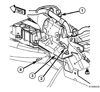
- Disconnect the instrument panel wire harness connector (1) from the terminal of the park brake switch (2) located on the outboard side of the park brake lever mechanism.
- Remove the screw (4) that secures the switch to the park brake lever bracket (3).
-
Remove the switch from the park brake lever bracket.
INSTALLATION
To avoid serious or fatal injury
on vehicles equipped with airbags, disable the Supplemental Restraint
System (SRS) before attempting any steering wheel, steering column,
airbag, seat belt tensioner, impact sensor or instrument panel component
diagnosis or service. Disconnect and isolate the battery negative
(ground) cable, then wait two minutes for the system capacitor to
discharge before performing further diagnosis or service. This is
the only sure way to disable the SRS. Failure to take the proper precautions
could result in accidental airbag deployment.
WARNING:
|
- Position park brake switch (2) onto the inboard side of the park brake lever bracket (3). Be certain to engage the locating pin on the side of the switch insulator into the locating slot in the lever bracket.
- Install and tighten the screw (4) that secures the switch to the lever bracket. Tighten the screw to 2.5 N·m (24 in. lbs.).
- Reconnect the instrument panel wire harness connector (1) to the terminal of the switch.
- Reinstall the console onto the floor panel transmission tunnel. (Refer to 23 - Body/Interior/CONSOLE, Center - Installation) .
- Reconnect the battery negative cable.
-
Turn the ignition switch to the ON position and check for proper brake indicator operation with the parking brake applied, then release the parking brake and check that the brake indicator extinguishes.