COVER(S), Engine Timing
REMOVAL
 |
- Disconnect and isolate the negative battery cable.
-
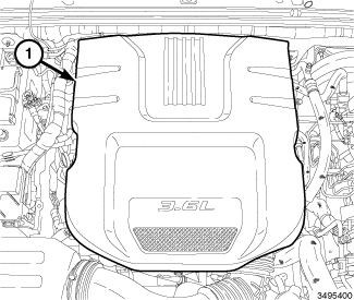
Remove the engine cover (1).
-
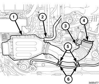
Remove the air cleaner body (1) (Refer to 09 - Engine/Air Intake System/BODY, Air Cleaner - Removal)
.
- Drain the cooling system (Refer to 07 - Cooling - Standard Procedure) .
-
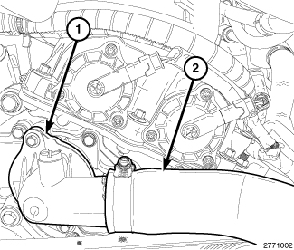
Remove the upper radiator hose (2) and thermostat housing (1) (Refer to 07 - Cooling/Engine/THERMOSTAT - Removal)
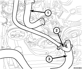
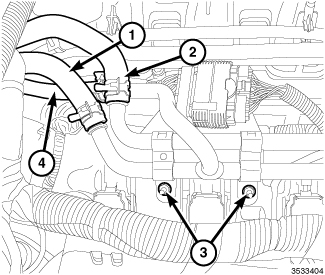
- Remove the heater core supply hose (1) from the coolant outlet housing.
- Remove the heater core return hose (2) from the water pump housing.
-
Remove the lower radiator hose (3) from the water pump housing.
-
Remove two nuts (3) and reposition the heater core supply tube.
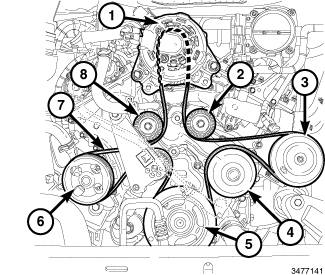
- Remove the generator (1) (Refer to 08 - Electrical/8F - Engine Systems/Charging/GENERATOR - Removal) .
- Remove the accessory drive belt (7) (Refer to 07 - Cooling/Accessory Drive/BELT, Serpentine - Removal)
- Remove the accessory drive belt tensioner (Refer to 07 - Cooling/Accessory Drive/TENSIONER, Belt - Removal) .
- Remove the accessory idler pulleys (2 and 8) (Refer to 07 - Cooling/Accessory Drive/PULLEY, Idler - Removal)
- Remove the power steering pump pulley (6) (Refer to 19 - Steering/Pump/PULLEY, Power Steering Pump - Removal) .
- Remove the crankshaft vibration damper (5) (Refer to 09 - Engine/Engine Block/DAMPER, Vibration - Removal) .
- Remove the upper intake manifold (Refer to 09 - Engine/Manifolds/MANIFOLD, Intake - Removal) .
- Remove the right and left cylinder head covers (Refer to 09 - Engine/Cylinder Head/COVER(S) , Cylinder Head - Removal).
-
Remove the upper oil pan (Refer to 09 - Engine/Lubrication/PAN, Oil - Removal)
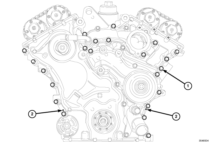
NOTE: It is not necessary to remove the water pump or the coolant outlet housing for engine timing cover removal.
-
Remove only the twenty-two highlighted M6 bolts (1).
-
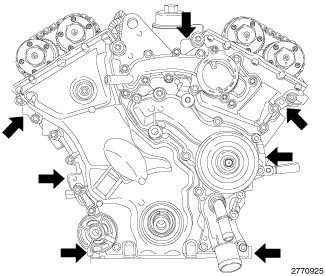
Using the seven indicated pry points, carefully remove the timing cover.
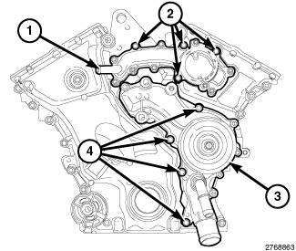
- If required, remove the remaining four M6 bolts (2) and the coolant outlet housing (1) from the engine timing cover.
-
If required, remove the remaining four M6 bolts (4) and the water pump (3) from the engine timing cover.
CAUTION: Do not use oil based liquids, wire brushes, abrasive wheels or metal scrapers to clean the engine gasket surfaces. Use only isopropyl (rubbing) alcohol, along with plastic or wooden scrapers. Improper gasket surface preparation may result in engine fluid leakage.
-
Remove all residual sealant from the timing chain cover, cylinder head and engine block mating surfaces (Refer to 09 - Engine - Standard Procedure)
-
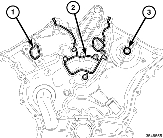
Remove and discard the coolant outlet housing gasket (1), the water pump gasket (2) and the O-ring (3).
INSTALLATION
|
- If removed, install the coolant outlet housing (1) to the timing cover with a new gasket using only the four bolts (2) shown tightened to 12 N·m (106 in. lbs.).
-
If removed, install
the water pump (3) to the timing cover using only the four bolts (4)
shown tightened to 12 N·m (106 in. lbs.) (Refer to 07 - Cooling/Engine/PUMP,
Water - Installation)
.
-
Install the coolant
outlet housing gasket (1), the water pump gasket (2) and the O-ring
(3).
-
Clean the engine timing
cover, cylinder head and block mating surfaces with isopropyl alcohol
in preparation for sealant application.
CAUTION: Engine assembly requires the use of a unique sealant that is compatible with engine oil. Using a sealant other than Mopar® Threebond Engine RTV Sealant may result in engine fluid leakage.
CAUTION: Following the application of Mopar® Threebond Engine RTV Sealant to the gasket surfaces, the components must be assembled within 20 minutes and the attaching fasteners must be tightened to specification within 45 minutes. Prolonged exposure to the air prior to assembly may result in engine fluid leakage.
-
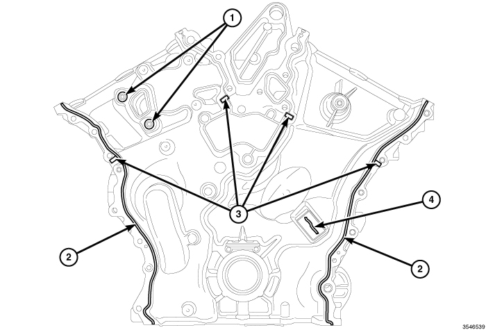
Apply a 2 to 3 mm wide
bead of Mopar® Threebond Engine RTV Sealant to the front cover as
shown in the following locations:
- Two cylinder head bosses (1)
- Right and left flanges (2)
- Four cylinder head to engine block T-joints (3)
-
Cover to right cam
chain tensioner gap (4)
- Align the locator pins (2) on the engine block to the engine timing cover and install the cover.
-
Install and tighten
the twenty-two highlighted M6 bolts (1) to 12 N·m (106 in. lbs.).
- Install the upper and lower oil pans (Refer to 09 - Engine/Lubrication/PAN, Oil - Installation) .
- Install the right and left cylinder head covers (Refer to 09 - Engine/Cylinder Head/COVER(S) , Cylinder Head - Installation).
- Install the upper intake manifold (Refer to 09 - Engine/Manifolds/MANIFOLD, Intake - Installation) .
- Install the crankshaft vibration damper (5) (Refer to 09 - Engine/Engine Block/DAMPER, Vibration - Installation) .
- Install the accessory idler pulleys (2 and 8) (Refer to 07 - Cooling/Accessory Drive/PULLEY, Idler - Installation) .
- Install the accessory drive belt tensioner (Refer to 07 - Cooling/Accessory Drive/TENSIONER, Belt - Installation) .
-
Install the generator
(1) and accessory drive belt (7) (Refer to 08 - Electrical/8F - Engine Systems/Charging/GENERATOR
- Installation)
.
-
Install the heater
core tube assembly to the right upper intake manifold support bracket
with two nuts (3) tightened to 12 N·m (106 in. lbs.).
- Connect the heater core supply hose (1) to the coolant outlet housing.
- Connect the heater core return hose (2) to the engine coolant pump housing.
-
Install the lower radiator
hose (3) to the engine coolant pump housing.
-
Install the thermostat
housing (1) and upper radiator hose (2) (Refer to 07 - Cooling/Engine/THERMOSTAT
- Removal)
-
Install the air cleaner
body (1) (Refer to 09 - Engine/Air
Intake System/BODY, Air Cleaner - Installation)
.
- If removed, install the oil filter and fill the engine crankcase with the proper oil to the correct level (Refer to 09 - Engine/Lubrication/OIL - Standard Procedure)
- Install the engine cover (1).
- Connect the negative battery cable and tighten nut to 5 N·m (45 in. lbs.).
- Fill the cooling system (Refer to 07 - Cooling - Standard Procedure) .
-
Run the engine until
it reaches normal operating temperature. Check cooling system for
correct fluid level (Refer to
07 - Cooling - Standard Procedure)