Dashboard Removal/Installation
Dashboard Removal/Installation
SRS components are located in this area. Review the SRS component locations LHD, SRS components locations RHD and the precautions and procedures in the SRS section before performing repairs or service.NOTE:
- When prying with a flat-tip screwdriver, wrap it with protective tape, and apply protective tape around the related parts to prevent damage.
- Have an assistant help you when removing and installing the dashboard.
- Take care not to scratch the dashboard, body and other related parts.
- Put on gloves to protect your hands.
| 1. | Disconnect the negative battery cable, and wait at least 3 minutes before beginning work. |
| 2. | Remove these items: |
| 3. | Remove the screw (A) and release the clip (B), then remove the driver's center lower cover (C). LHD is shown; RHD is symmetrical.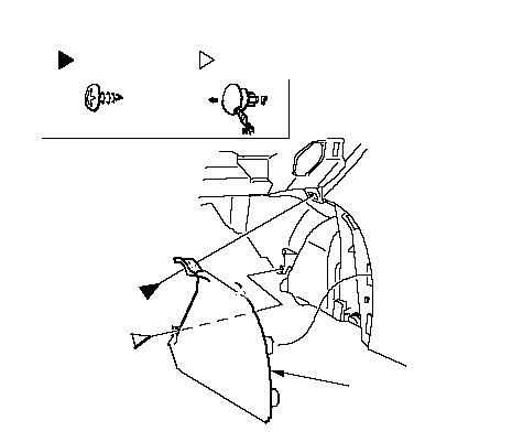 Fastener LocationsA: Screw, 1B: Clip, 1ABC Fastener LocationsA: Screw, 1B: Clip, 1ABC |
| 4. | Release the clip, then remove the pasenger's center lower cover (A) and the rear vent duct (B). LHD is shown; RHD is symmetrical.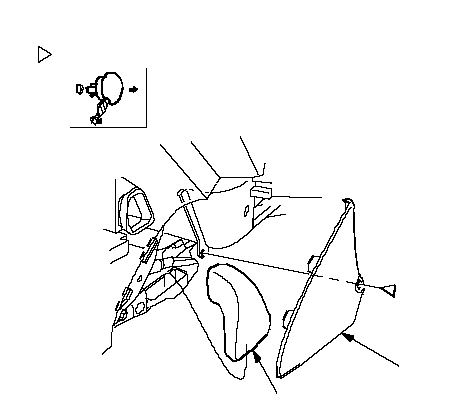 Fastener Location: Clip, 1BA Fastener Location: Clip, 1BA |
Driver's side:
| 5. | From under the dash, disconnect the interior wire harness connector (A) (with sunroof), clutch switch connectors (B) (on LHD M/T model) or clutch sub wire harness connector (C) (on RHD M/T model), brake switch connector (D), floor wire harness connectors (E), engine compartment wire harness connectors (F), inertia switch connector (G), and disconnect the dashboard wire harness connectors (H) from the under-dash fuse/relay box (I), then release the wire harness clip. On auto A/C model, disconnect the air hose (J). LHD: 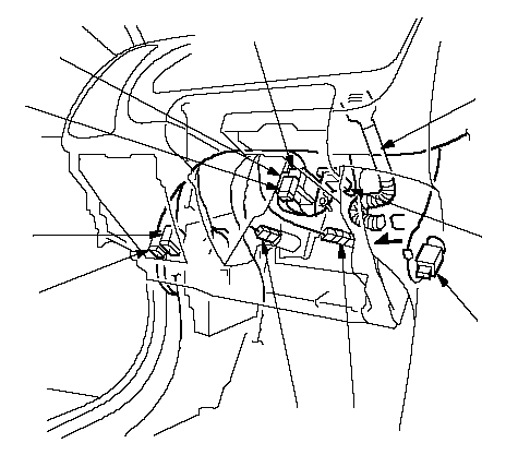 BEFEDJFFFG BEFEDJFFFG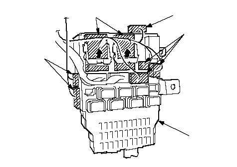 IHAHH IHAHHRHD: 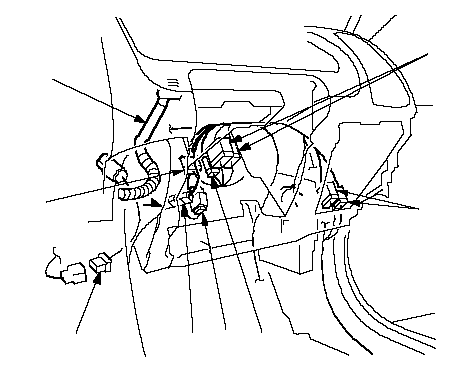 DEFFFJCG DEFFFJCG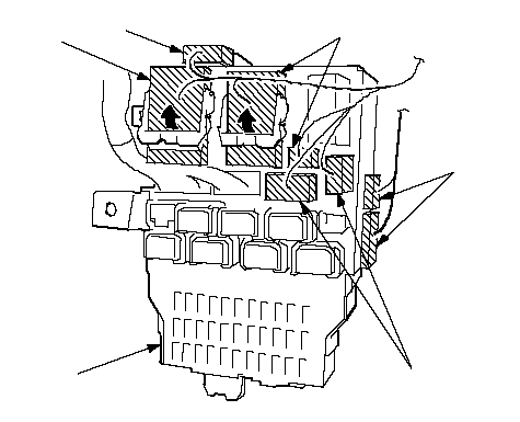 HAHIHH HAHIHH |
Middle portion (shift lever portion):
| 6. | Disconnect the parking brake switch connector (A), SRS unit connector (B), radio antenna connector (C), antenna lead (D), A/C subharness connector (E), then release the wire harness clip (F), and if applicable, release the harness clamp (G). Using a Torx T30 bit, remove the ground bolt (H). On A/T model, disconnect the parking pin switch connector (I) and shift lock solenoid connector (J). LHD (A/T): 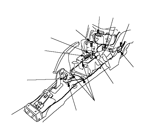 CBDAJFH CBDAJFH6 x 1.0 mm 9.8 N·m (1.0 kgf·m, 7.2 lbf·ft)EFFI LHD (M/T): 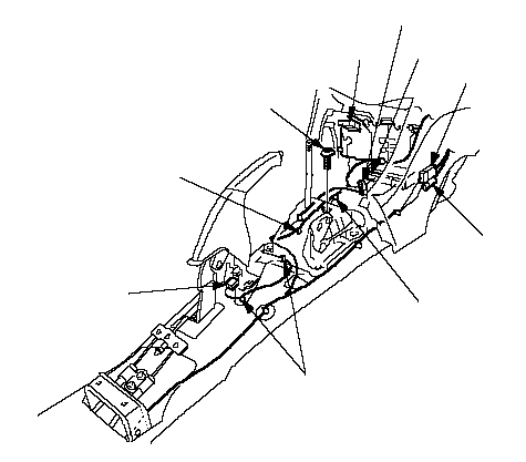 CGDAFH CGDAFH6 x 1.0 mm 9.8 N·m (1.0 kgf·m, 7.2 lbf·ft)EFFB RHD: 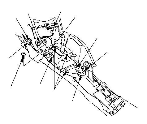 CBDAFH CBDAFH6 x 1.0 mm 9.8 N·m (1.0 kgf·m, 7.2 lbf·ft)EIJFF |
Middle portion (passenger's side):
| 7. | From under the dash, disconnect the ECM/PCM connectors (A), power transistor connector (B), and engine wire harness connectors (C), then release the wire harness clips (D). LHD is shown; RHD is symmetrical.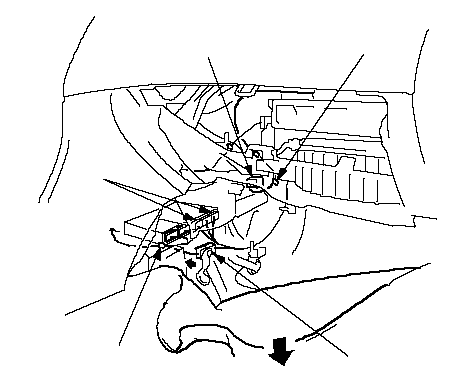 CBDAD CBDAD |
Passenger's side:
| 8. | From under the dash, disconnect the passenger's door wire harness connectors (A), floor wire harness connectors (B), interior wire harness connector (C) and blower motor connector (D). LHD is shown; RHD is symmetrical.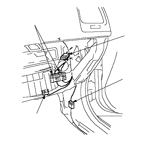 ADBC ADBC |
| 9. | Detach all of the harness and connector clips. |
| 10. | Remove bolt (A), detach the connectors (B) and harness clip (C) (RHD), then remove the brake pedal support member (D). LHD: 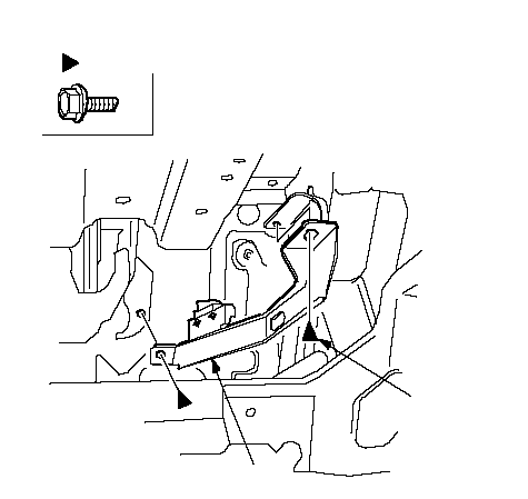 Fastener Locations: Bolt, 2AA Fastener Locations: Bolt, 2AA8 x 1.25 mm 22 N·m (2.2 kgf·m, 16 lbf·ft)DA RHD: 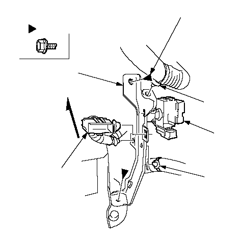 Fastener Locations: Bolt, 2ABCA Fastener Locations: Bolt, 2ABCA8 x 1.25 mm 22 N·m (2.2 kgf·m, 16 lbf·ft)CBDUpwardA |
| 11. | From outside the driver's door, remove the caps (A), then remove the bolts (B, C, D), and clips (E) and lift up on the dashboard (F) to release it from the guide pins (G, H).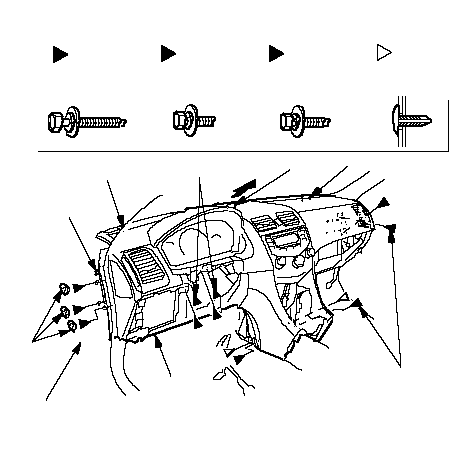 Fastener Locations: Bolt, 3B: Bolt, 2C: BoltDLHD, 6 Fastener Locations: Bolt, 3B: Bolt, 2C: BoltDLHD, 6RHD, 4: Clip, 2E8 x 1.25 mm 22 N·m (2.2 kgf·m, 16 lbf·ft)ABBBGHD (LHD)HHDDEC8 x 1.25 mm 22 N·m (2.2 kgf·m, 16 lbf·ft)CEDDF |
| 12. | Carefully remove the dashboard through the front door opening. |
| 13. | Install the dashboard in the reverse order of removal, and note these items:
|