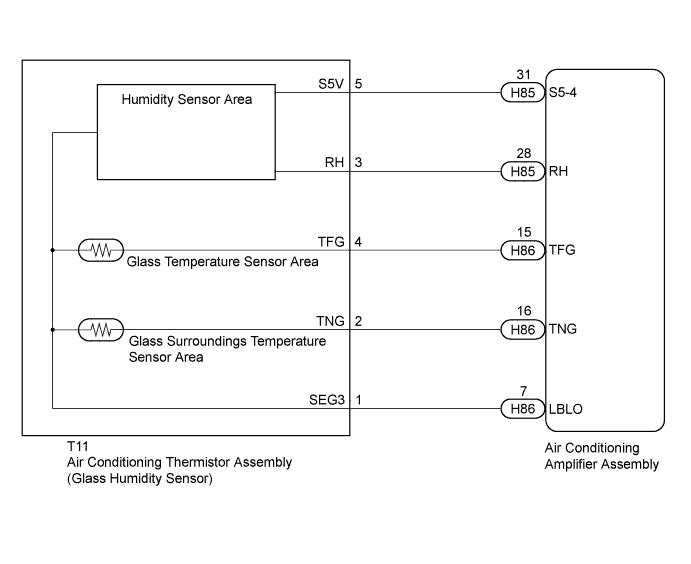
DTC B14AA Glass Humidity Sensor Circuit |
| DTC No. | DTC Detection Condition | Trouble Area |
| B14AA | Open or short in glass humidity sensor circuit |
|
| 1.READ VALUE USING INTELLIGENT TESTER |
Connect the intelligent tester to the DLC3.
Turn the power switch on (IG).
Turn the intelligent tester on.
Enter the following menus: Body / Air Conditioner / Data List.
Check the value(s) by referring to the table below.
| Tester Display | Measurement Item/Range | Normal Condition | Diagnostic Note |
| Glass Humidity | Glass humidity/ Min.: 0 (%) Max.: 200 (%) | Actual glass humidity displayed | - |
| Result | Proceed to |
| NG | A |
| OK (When troubleshooting according to Problem Symptoms Table) | B |
| OK (When troubleshooting according to the DTC) | C |
|
| ||||
|
| ||||
| A | |
 |
| 2.INSPECT AIR CONDITIONING AMPLIFIER ASSEMBLY |
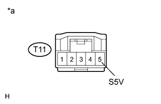 |
Disconnect the T11 air conditioning thermistor assembly (glass humidity sensor) connector.
Measure the voltage according to the value(s) in the table below.
| Tester Connection | Condition | Specified Condition |
| T11-5 (S5V) - Body ground | Power switch on (IG) | 4.5 to 5.5 V |
| *a | Front view of wire harness connector (to Air Conditioning Thermistor Assembly (Glass Humidity Sensor)) |
|
| ||||
| OK | |
|
| 3.INSPECT AIR CONDITIONING THERMISTOR ASSEMBLY (GLASS HUMIDITY SENSOR) |
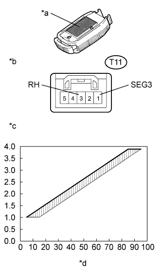 |
Remove the air conditioning thermistor assembly (glass humidity sensor) with the connector still connected (Click here).
Turn the power switch on (IG).
Measure the voltage according to the value(s) in the table below.
| Tester Connection | Condition | Specified Condition |
| T11-1 (SEG3) - T11-3 (RH) | Power switch on (IG) Humidity is 5 to 15% | Approximately 1.01 V |
| T11-1 (SEG3) - T11-3 (RH) | Power switch on (IG) Humidity is 15 to 25% | Approximately 1.37 V |
| T11-1 (SEG3) - T11-3 (RH) | Power switch on (IG) Humidity is 25 to 35% | Approximately 1.73 V |
| T11-1 (SEG3) - T11-3 (RH) | Power switch on (IG) Humidity is 35 to 45% | Approximately 2.09 V |
| T11-1 (SEG3) - T11-3 (RH) | Power switch on (IG) Humidity is 45 to 55% | Approximately 2.45 V |
| T11-1 (SEG3) - T11-3 (RH) | Power switch on (IG) Humidity is 55 to 65% | Approximately 2.81 V |
| T11-1 (SEG3) - T11-3 (RH) | Power switch on (IG) Humidity is 65 to 75% | Approximately 3.17 V |
| T11-1 (SEG3) - T11-3 (RH) | Power switch on (IG) Humidity is 75 to 85% | Approximately 3.53 V |
| T11-1 (SEG3) - T11-3 (RH) | Power switch on (IG) Humidity is 85 to 95% | Approximately 3.89 V |
| *a | Heat Conduction Sheet Part |
| *b | Component with harness connected (Air Conditioning Thermistor Assembly (Glass Humidity Sensor)) |
| *c | Voltage (V) |
| *d | Relative Humidity (%) |
|
| ||||
| OK | |
|
| 4.CHECK HARNESS AND CONNECTOR (AIR CONDITIONING AMPLIFIER - GLASS HUMIDITY SENSOR) |
Disconnect the T11 air conditioning thermistor assembly (glass humidity sensor) connector.
Disconnect the H85 and H86 air conditioning amplifier assembly connectors.
Measure the resistance according to the value(s) in the table below.
| Tester Connection | Condition | Specified Condition |
| T11-3 (RH) - H85-28 (RH) | Always | Below 1 Ω |
| T11-3 (RH) - Body ground | Always | 10 kΩ or higher |
| T11-1 (SEG3) - H86-7 (LBLO) | Always | Below 1 Ω |
| T11-1 (SEG3) - Body ground | Always | 10 kΩ or higher |
|
| ||||
| OK | ||
 | ||
| ||
| 5.CHECK HARNESS AND CONNECTOR (AIR CONDITIONING AMPLIFIER - GLASS HUMIDITY SENSOR) |
Disconnect the T11 air conditioning thermistor assembly (glass humidity sensor) connector.
Disconnect the H85 air conditioning amplifier assembly connector.
Measure the resistance according to the value(s) in the table below.
| Tester Connection | Condition | Specified Condition |
| T11-5 (S5V) - H85-31 (S5-4) | Always | Below 1 Ω |
| T11-5 (S5V) - Body ground | Always | 10 kΩ or higher |
|
| ||||
| OK | ||
| ||
| ||

