ADJUSTMENT
Removal / installation
| 1. INSPECT TIRES |

| 2. MEASURE VEHICLE HEIGHT |
- NOTICE:
- Before inspecting wheel alignment, adjust the vehicle height to the specified values.
| 3. INSPECT TOE-IN |
- Toe-in:
Toe-in (total)
A - B: 3 +- 2 mm (0.12 +- 0.08 in.)
| 4. ADJUST TOE-IN |
Loosen the toe adjust plate nut.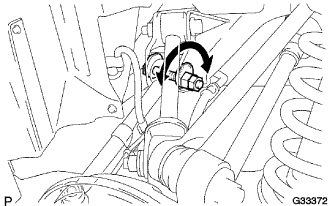

Turn the adjust cams by an equal amount to adjust toe-in.
- HINT:
- Try to adjust the toe-in to the center value.
- The toe-in will change by the following amount corresponding to each graduation of the cam:
Approx. 4.0 mm (0.16 in.)
- Try to adjust the toe-in to the center value.
Tighten the nut.
- Torque:
- 50 N*m{ 510 kgf*cm , 37 ft.*lbf }
| 5. INSPECT CAMBER |
Install a camber-caster-kingpin gauge or put the wheels on a wheel alignment tester.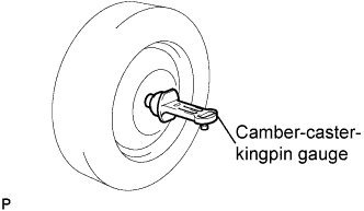
Inspect the camber.
- CAMBER:
Suspension Type
Camber Angle
Sports Suspension
-1°14'+-45'
(1.23°+-0.75°)
Normal Suspension
-1°14'+-45' (1.23°+-0.75°)*1
-1°1'+-45' (1.02°+-0.75°)*2
- HINT:
- *1 17 in., 18 in. wheel
- *2 16 in. wheel
- NOTICE:
- Inspect while the vehicle is empty.
- The maximum tolerance of right and left difference for the camber and caster is 30' (0.5°) or less.
- Inspect while the vehicle is empty.
| 6. INSPECT REAR SUSPENSION |
Inspect the rear suspension member.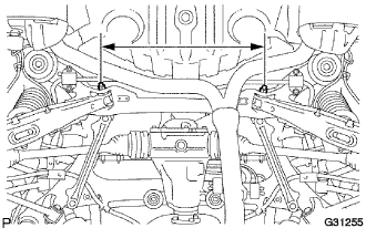
Measure the distance between the centers of the installation bolts of the rear No. 2 suspension arm assembly LH and RH.
- Standard:
- 508.6 to 514.6 mm (20.02 to 20.25 in.)
- HINT:
- If the distance is not within the specified range, replace the rear suspension member.
Visually inspect the press holes on the installation area of the rear upper No. 2 control arm assembly.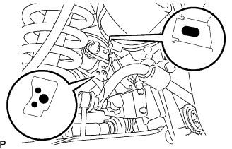
- Standard:
- The holes are not deformed.
- HINT:
- If the holes are deformed, replace the rear suspension member.
Inspect the rear No. 2 suspension arm assembly.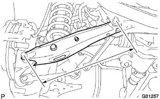
Measure the distance between the centers of the 2 installation bolts of the rear No. 2 suspension arm assembly.
- Standard:
- 433.4 to 434.4 mm (17.06 to 17.10 in.)
- HINT:
- If the distance is not within the specified range, replace the rear No. 2 suspension arm assembly.
Inspect the rear upper No. 2 control arm assembly.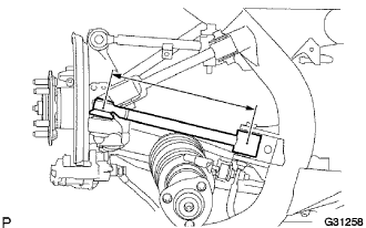
Measure the distance between the centers of the installation bolt of the rear upper No. 2 control arm assembly and the ball joint stud.
- Standard:
- 307.3 to 308.7 mm (12.1 to 12.2 in.)
- HINT:
- If the distance is not within the specified range, replace the rear upper No. 2 control arm assembly.
Inspect and adjust toe-in and camber.
Inspect toe-in and camber.
If the values are not within the specified ranges, adjust the installation bolt holding the rear suspension member to the vehicle body, or the bolt holding the upper control arm and rear suspension arm so that the values fall within the specified ranges.