Lexus IS250 · Service Manual BODY ELECTRICAL

Wiper and Washer Switch Circuit

Circuit diagnosis

DESCRIPTION

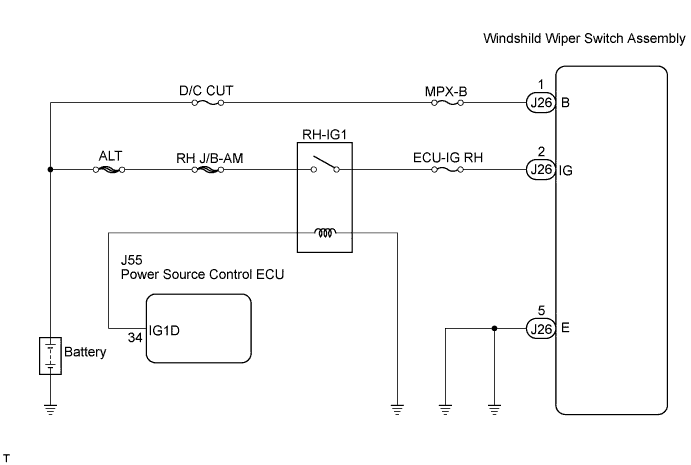
This circuit provides power to operate the windshield wiper switch assembly. The manual operation signals are sent to the main body ECU LH (cowl side J/B LH).

WIRING DIAGRAM

E119065E01

INSPECTION PROCEDURE

HINT:
Before starting the following procedure, check that multiplex communication system (MPX) DTCs are not output (Click here).


1. READ VALUE OF INTELLIGENT TESTER (WIPER SWITCH)
  1. Connect the intelligent tester to the DLC3.

  1. Turn the engine switch on (IG) and turn the intelligent tester main switch on.

  1. Select the items below in the DATA LIST, and read the displays on the intelligent tester.

    Combination Switch: 
    Item
    Measurement Item / Display (Range)
    Normal Condition
    Diagnostic Note
    F Washer SW
    Front washer switch / ON or OFF
    ON: Front washer switch ON
    OFF: Front washer switch OFF
    -
    F Wiper Mist SW
    Front wiper MIST switch / ON or OFF
    ON: Front wiper switch in MIST
    OFF: Wiper switch not in MIST
    -
    F Wiper Hi SW
    Front wiper HI switch / ON or OFF
    ON: Front wiper switch in HI
    OFF: Wiper switch not in HI
    -
    F Wiper Lo SW
    Front wiper LO switch / ON or OFF
    ON: Front wiper switch in LO
    OFF: Wiper switch not in LO
    -
    F Wiper Int SW
    Front wiper INT switch / ON or OFF
    ON: Front wiper switch in INT
    OFF: Wiper switch not in INT
    -
    IG SW Sig
    Engine switch signal / ON or OFF
    ON: Engine switch on (IG)
    OFF: Engine switch off
    -
    F Wiper Vol Pos
    Front wiper volume (sensitivity) / 0 to 90 degrees
    0 degrees: FR wiper volume "+" position
    27 degrees: Switch is turned one notch towards the "-" side from the FR wiper volume "+" position
    63 degrees: Switch is turned one notch towards the "+" side from the FR wiper volume "-" position
    90 degrees: FR wiper volume "-" position
    If the value is NG, replace the windshield wiper switch assembly (Click here).


NG
Go to step 2
OK

PROCEED TO NEXT CIRCUIT INSPECTION SHOWN IN PROBLEM SYMPTOMS TABLE

2. CHECK WINDSHIELD WIPER SWITCH ASSEMBLY (COMBINATION SWITCH ECU)

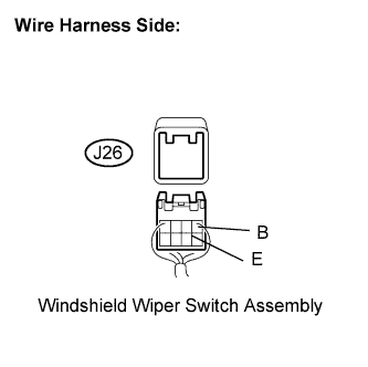
  1. E106806E08
    Disconnect the J26 windshield wiper switch assembly connector.

  1. Measure the voltage according to the value(s) in the table below.

    Standard voltage:
    Tester Connection
    Condition
    Specified Condition
    J26-1 (B) - J26-5 (E)
    Always
    10 to 14 V


NG
REPAIR OR REPLACE HARNESS OR CONNECTOR
OK

REPLACE WINDSHIELD WIPER SWITCH ASSEMBLY (COMBINATION SWITCH ECU)


← Wiper Motor Power Source CircuitRain Sensor Circuit →