Rain Sensor Circuit
Circuit diagnosis
DESCRIPTION
This circuit provides power to operate the rain sensor.The auto wiper system operates when the windshield wiper switch assembly is in the AUTO position.
The rain sensor is connected to other ECUs through the multiplex communication line (BEAN).
When the rain sensor detects raindrops in the detection area on the windshield glass, the sensor sends a wiper control signal according to the amount of raindrops to the main body ECU LH (cowl side J/B LH).
The rain sensor also sends signals to the adaptive radar cruise control system and the mirror defogger system.
WIRING DIAGRAM
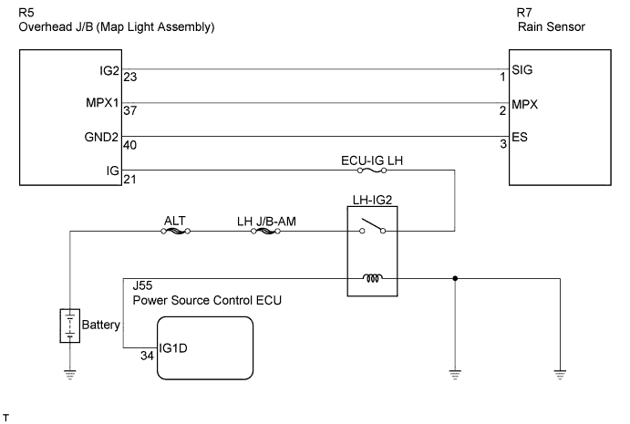

INSPECTION PROCEDURE
- HINT:
- Before starting the following procedure, check that multiplex communication system (MPX) DTCs are not output (Click here).
- Before starting the following procedure, verify that the rain sensor tape is correctly installed.
- Before starting the following procedure, check that multiplex communication system (MPX) DTCs are not output (Click here).
| 1. CHECK RAIN SENSOR |

Disconnect the R7 rain sensor connector.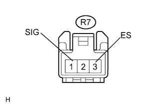
Measure the voltage according to the value(s) in the table below.
- Standard voltage:
Tester Connection
Condition
Specified Condition
R7-1 (SIG) - R7-3 (ES)
Engine switch on (IG)
10 to 14 V
Engine switch off
Below 1 V
|
|
||||

| OK | ||
 |
||
| ||
| 2. CHECK HARNESS AND CONNECTOR (RAIN SENSOR - OVERHEAD J/B) |
Disconnect the R5 overhead J/B connector.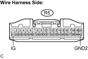
Measure the voltage according to the value(s) in the table below.
- Standard voltage:
Tester Connection
Condition
Specified Condition
R5-21 (IG) - R5-40 (GND2)
Engine switch on (IG)
10 to 14 V
Engine switch off
Below 1 V
|
|
||||
| OK | ||
|
||
| ||