Headlight Cleaner Switch Circuit
Circuit diagnosis
DESCRIPTION
This circuit detects the conditions (on or off) of the headlight cleaner switch.The headlight cleaner control relay receives the following signals:
- Headlight cleaner switch signal
- Headlight operating signal
- Daytime running light operating signal
- Front washer motor operating signal
WIRING DIAGRAM
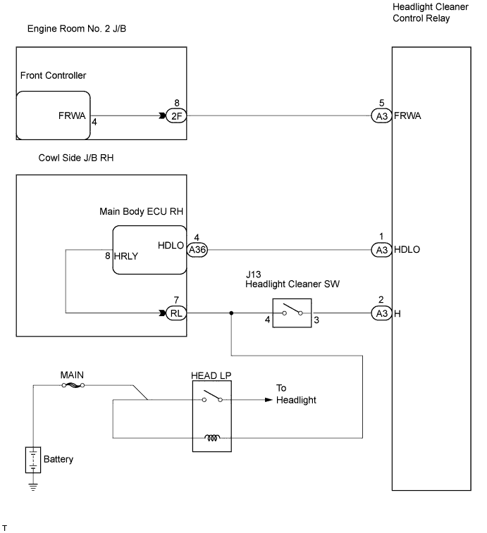

INSPECTION PROCEDURE
| 1. CHECK MAIN BODY ECU RH (COWL SIDE J/B RH) (HDLO SIGNAL) |

Measure the voltage according to the value(s) in the table below.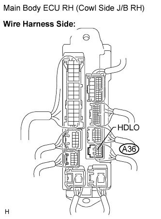
- Standard voltage:
Tester Connection
Condition
Specified Condition
A36-4 (HDLO) - Body ground
Engine switch on (IG) and light control switch OFF
10 to 14 V
A36-4 (HDLO) - Body ground
Engine switch on (IG) and light control switch in HEAD position
Below 1 V
|
|
||||

| OK | |
 |
| 2. INSPECT FRONT CONTROLLER (ENGINE ROOM NO. 2 J/B) (FRWA SIGNAL) |
Measure the voltage according to the value(s) in the table below.
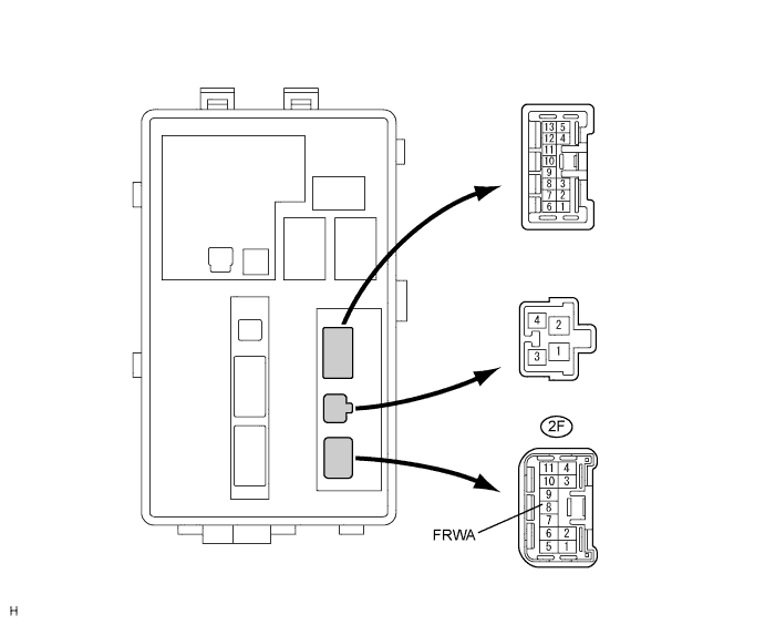
- Standard voltage:
Tester Connection
Condition
Specified Condition
2F-8 (FRWA) - Body ground
Engine switch on (IG) and front washer is stopped
10 to 14 V
2F-8 (FRWA) - Body ground
Engine switch on (IG) and front washer is operated
Below 1 V
|
|
||||
| OK | |
|
| 3. CHECK HEADLIGHT CLEANER SWITCH ASSEMBLY |
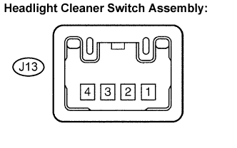 |
Disconnect the connector from the headlight cleaner switch assembly.
Measure the resistance according to the value(s) in the table below.
- Standard resistance:
Tester Connection
Condition
Specified Condition
4 - 3
Headlight cleaner switch not pushed
10 kΩ or higher
4 - 3
Headlight cleaner switch pushed
Below 1 Ω
|
|
||||

| OK | |
|
| 4. CHECK MAIN BODY ECU RH (COWL SIDE J/B RH) (HRLY SIGNAL) |
Measure the voltage according to the value(s) in the table below.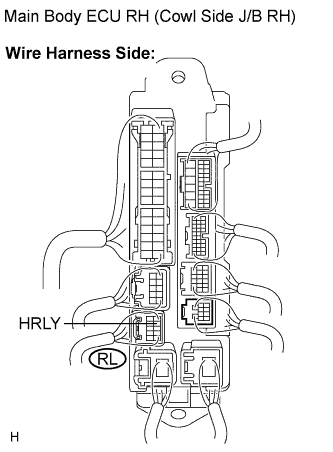
- Standard voltage:
Tester Connection
Condition
Specified Condition
RL-7 (HRLY) - Body ground
Engine switch on (IG) and headlight cleaner switch OFF
Below 1 V
RL-7 (HRLY) - Body ground
Engine switch on (IG) and headlight cleaner switch ON
10 to 14 V
|
|
||||
| OK | ||
 |
||
| ||
| 5. CHECK HARNESS AND CONNECTOR (HEADLIGHT CLEANER CONTROL RELAY - MAIN BODY ECU RH) |
Disconnect the A3 headlight cleaner control relay connector.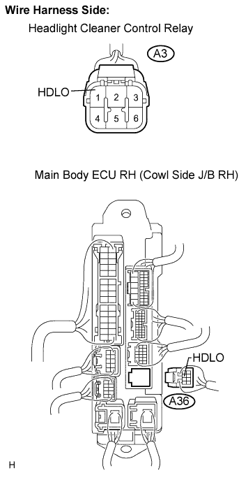
Disconnect the A36 main body ECU RH (cowl side J/B RH) connector.
Measure the resistance according to the value(s) in the table below.
- Standard resistance:
Tester Connector
Condition
Specified Condition
A3-1 (HDLO) - A36-1 (HDLO)
Always
Below 1 Ω
A3-1 (HDLO) - Body ground
Always
10 k Ω or higher
|
|
||||
| OK | ||
|
||
| ||
| 6. CHECK HARNESS AND CONNECTOR (HEADLIGHT CLEANER CONTROL RELAY - FRONT CONTROLLER) |
Disconnect the 2F front controller (engine room No. 2 J/B) connector.
Measure the resistance according to the value(s) in the table below.
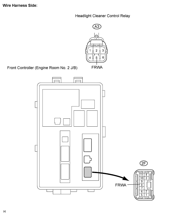
- Standard resistance:
Tester Connection
Condition
Specified Condition
A3-5 (FRWA) - 2F-8 (FRWA)
Always
Below 1 Ω
A3-5 (FRWA) - Body ground
Always
10 k Ω or higher
|
|
||||
| OK | ||
|
||
| ||
| 7. CHECK HARNESS AND CONNECTOR (HEADLIGHT CLEANER SWITCH ASSEMBLY - MAIN BODY ECU RH) |
Disconnect the J13 headlight cleaner switch assembly connector.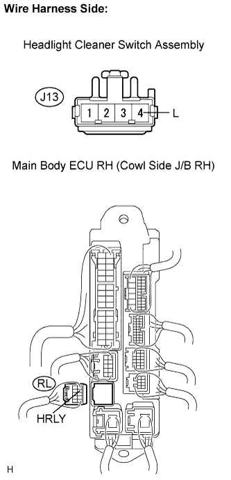
Disconnect the RL main body ECU RH (cowl side J/B RH) connector.
Measure the resistance according to the value(s) in the table below.
- Standard resistance:
Tester Connection
Condition
Specified Condition
J13-4 (L) - RL-7 (HRLY)
Always
Below 1 Ω
RL-7 (HRLY) - Body ground
Always
10 k Ω or higher
|
|
||||
| OK | ||
|
||
| ||