INSTALLATION
Removal / installation
| 1. INSTALL BRAKE MASTER CYLINDER PUSH ROD CLEVIS |

Temporarily install the push rod clevis with the lock nut.
Adjust and fully tighten the push rod clevis with the lock nut (Click here).
| 2. INSTALL BRAKE VACUUM CHECK VALVE ASSEMBLY |
Install the grommet and check valve assembly.
| 3. INSTALL BRAKE BOOSTER GASKET |
Install a new brake booster gasket to the brake booster assembly.
| 4. INSTALL BRAKE BOOSTER ASSEMBLY |
Install the brake booster assembly with the 4 nuts.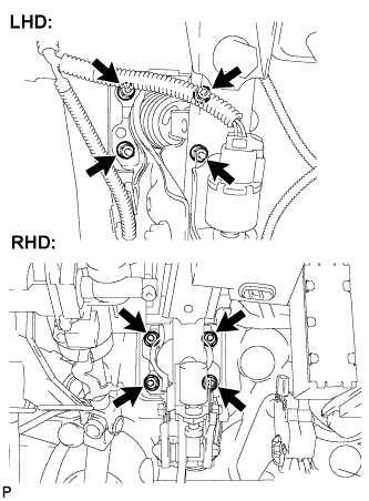

- Torque:
- 12.7 N*m{ 130 kgf*cm , 9 ft.*lbf }
- NOTICE:
- Do not damage the brake lines.
Connect the vacuum hose with the clip.
| 5. INSTALL BRAKE MASTER CYLINDER PUSH ROD CLEVIS |
Apply lithium soap base glycol grease to the clevis pin.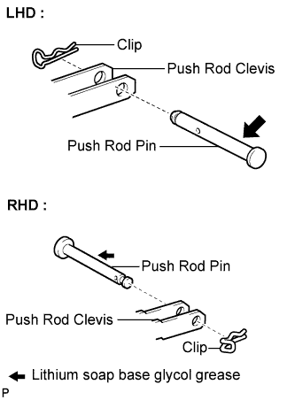
Install the push rod clevis to the brake pedal support assembly with the clevis pin and a new clip.
| 6. INSTALL BRAKE PEDAL RETURN SPRING |
Install the brake pedal return spring.
| 7. INSTALL BRAKE MASTER CYLINDER SUB-ASSEMBLY |
Install a new O-ring to the brake master cylinder sub-assembly.
Install the brake master cylinder sub-assembly to the booster assembly with the 2 nuts.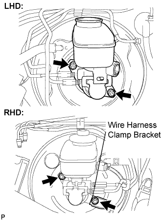
- Torque:
- 12.5 N*m{ 127 kgf*cm , 9 ft.*lbf }
Install the brake actuator assembly to the actuator bracket with the 2 cap nuts.
- Torque:
- 5.5 N*m{ 55 kgf*cm , 48 in.*lbf }
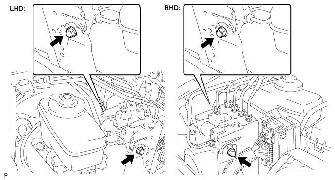
Using SST, connect the 2 brake lines to the brake master cylinder sub-assembly.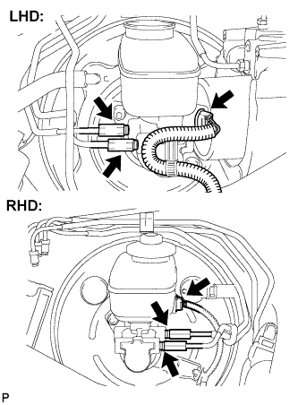
- SST
- 09023-00101
- Torque:
- 15 N*m{ 155 kgf*cm , 11 ft.*lbf }
Engage the clamp and connect the warning switch connector.
| 8. CONNECT CLUTCH RESERVOIR HOSE (for Manual Transmission) |
Connect the clutch reservoir hose with the clamp.
| 9. INSTALL BRAKE ACTUATOR ASSEMBLY WITH BRACKET |
Install the actuator assembly with bracket to the body with the 2 bolts and nut.
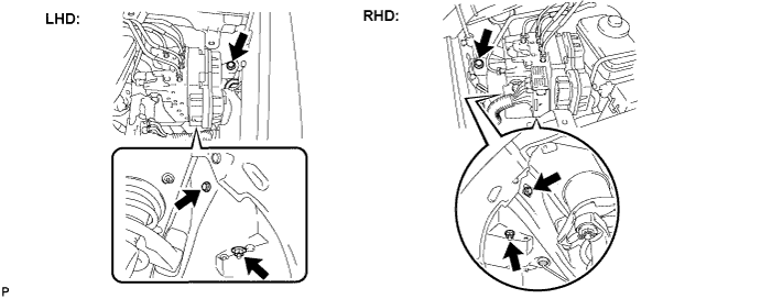
- Torque:
- 19 N*m{ 195 kgf*cm , 14 ft.*lbf }
- NOTICE:
- Do not to damage the brake tubes.
Install the grommet to the body.
- NOTICE:
- Make sure that the grommet is installed correctly.
Temporarily tighten each brake tube to the correct positions of the brake actuator assembly with bracket as shown in the illustration.
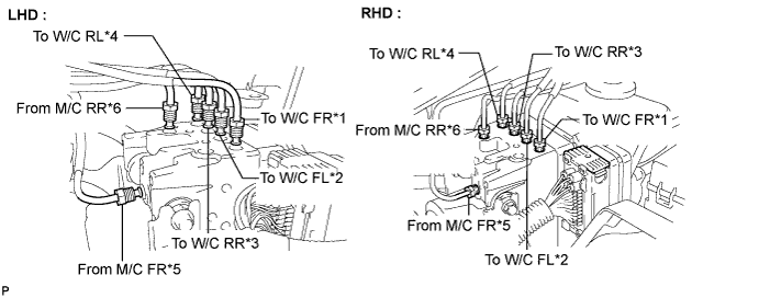
- HINT:
- *1: To Front Wheel Cylinder RH
- *2: To Front Wheel Cylinder LH
- *3: To Rear Wheel Cylinder RH
- *4: To Rear Wheel Cylinder LH
- *5: From Front Master Cylinder
- *6: From Rear Master Cylinder
- *1: To Front Wheel Cylinder RH
Using SST, fully tighten each brake tube.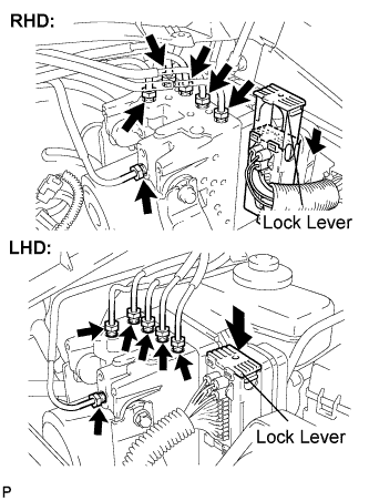
- SST
- 09023-00101
- Torque:
- 15 N*m{ 155 kgf*cm , 11 ft.*lbf }
Connect the actuator connector.
- NOTICE:
- Make sure that the connector is locked securely.
| 10. INSTALL NO. 3 ENGINE ROOM RELAY BLOCK |
Install the No. 3 engine room relay block with the bolt and nut.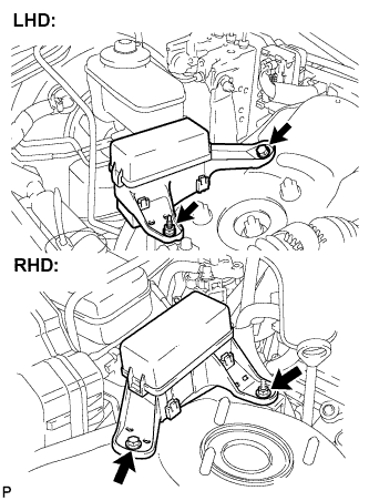
- Torque:
- 12.5 N*m{ 127 kgf*cm , 9 ft.*lbf }
| 11. CONNECT BATTERY NEGATIVE TERMINAL |
| 12. FILL RESERVOIR WITH BRAKE FLUID |
Fill the reservoir with brake fluid.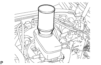
- Fluid:
- SAE J1703 or FMVSS No. 116 DOT3
| 13. BLEED MASTER CYLINDER |
- HINT:
- If the master cylinder is reinstalled or if the reservoir becomes empty, bleed the air from the master cylinder.
- To prevent paint damage due to brake fluid, cover the painted surface with a shop rag or a piece of cloth.
- If the master cylinder is reinstalled or if the reservoir becomes empty, bleed the air from the master cylinder.
Disconnect the 2 brake lines from the master cylinder.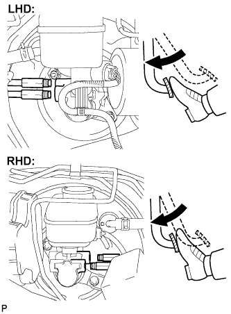
Slowly depress the brake pedal and hold it (*1).
Cover the 2 outer holes with fingers, and release the brake pedal (*2).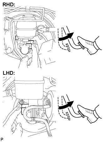
Repeat (*1) and (*2) 3 or 4 times.
Using SST, connect the brake lines to the master cylinder.
- SST
- 09023-00101
- Torque:
- 15 N*m{ 155 kgf*cm , 11 ft.*lbf }
| 14. BLEED BRAKE LINE |
- NOTICE:
- Bleed the brake line at the wheel furthest from the master cylinder.
Connect the vinyl tube to the bleeder plug.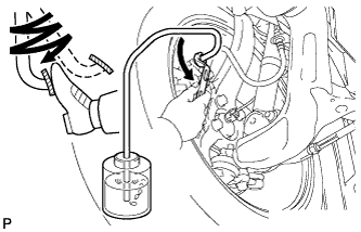
Depress the brake pedal several times, then loosen the bleeder plug with the pedal depressed (*3).
When fluid no longer comes out, tighten the bleeder plug, then release the brake pedal (*4).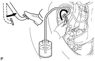
Repeat (*3) and (*4) until all the air in the fluid is completely bled out.
Using SST, tighten the bleeder plug completely.
- SST
- 09023-00101
- Torque:
- 11 N*m{ 110 kgf*cm , 8 ft.*lbf }
Repeat the above procedures for each wheel to bleed the air from the brake line.
| 15. BLEED BRAKE ACTUATOR ASSEMBLY |
- NOTICE:
- After bleeding the air from the brake system, if the correct height or feel of the brake pedal cannot be obtained, bleed the air from the brake actuator assembly with the intelligent tester by following the procedures below.
Depress the brake pedal more than 20 times with the engine switch off.
Connect the intelligent tester to the DLC3, then turn the engine switch on (IG).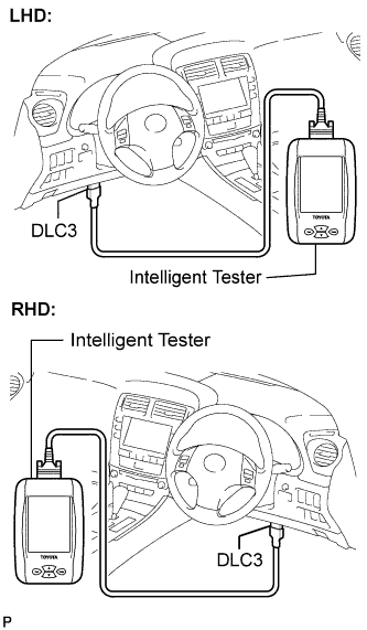
- NOTICE:
- Do not start the engine.
Turn the intelligent tester power on and select "AIR BLEEDING" on the screen.
- NOTICE:
- Refer to the intelligent tester operator's manual for further details.
- Bleed the brake actuator assembly by following the steps displayed on the intelligent tester.
- Refer to the intelligent tester operator's manual for further details.
Bleed the air from the actuator according to "Step 1: Increase" on the intelligent tester display.
- NOTICE:
- Make sure that the master cylinder reservoir tank does not become empty of brake fluid.
Connect a vinyl tube to either one of the bleeder plugs.
Depress the brake pedal several times, then loosen the bleeder plug connected to the vinyl tube with the pedal depressed (*5).
When fluid no longer comes out, tighten the bleeder plug, then release the brake pedal (*6).
Repeat (*5) and (*6) until all the air in the fluid is completely bled.
Using SST, tighten the bleeder plug completely.
- SST
- 09023-00101
- Torque:
- 11 N*m{ 110 kgf*cm , 8 ft.*lbf }
Repeat the above procedures for the rest of the wheels to bleed the air from the brake lines.
Bleed the air from the suction line according to "Step 2: Inhalation" on the intelligent tester display.
- NOTICE:
- Bleed the suction line by following the steps displayed on the intelligent tester.
- Make sure that the master cylinder reservoir tank does not become empty of brake fluid.
- Bleed the suction line by following the steps displayed on the intelligent tester.
Connect a vinyl tube to the bleeder plug at the right front wheel or the right rear wheel and loosen the bleeder plug.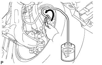
Operate the brake actuator assembly to bleed the air using the intelligent tester (*7).
- NOTICE:
- The operation stops automatically in 4 seconds.
- At this time, be sure to release the brake pedal.
- The operation stops automatically in 4 seconds.
Check that the operation has stopped by referring to the intelligent tester display and tighten the bleeder plug (*8).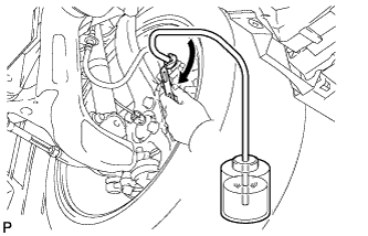
Repeat (*7) and (*8) until all the air in the fluid is completely bled out.
Using SST, tighten the bleeder plug completely.
- SST
- 09023-00101
- Torque:
- 11 N*m{ 110 kgf*cm , 8 ft.*lbf }
For the rest of the wheels, bleed the air in the same way as stated in the above procedures.
Bleed the air from the pressure reduction line according to "Step 3: Decrease" on the intelligent tester display.
- NOTICE:
- Bleed the pressure reduction line by following the steps displayed on the intelligent tester.
- Make sure that the master cylinder reservoir tank does not become empty of brake fluid.
- Bleed the pressure reduction line by following the steps displayed on the intelligent tester.
Connect a vinyl tube to either one of the bleeder plugs.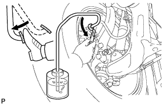
Loosen the bleeder plug (*9).
Using the intelligent tester, operate the brake actuator assembly, completely depress the brake pedal and hold it.
- NOTICE:
- The operation stops automatically after 4 seconds. When this operation will be repeated continuously, allow an interval of at least 20 seconds between each bleeding operation.
- When the operation is completed, the brake pedal will go down slightly. This is a normal phenomenon due to the opening of the solenoid.
- During this procedure, the brake pedal will seem heavy. It is necessary to completely depress it, so that brake fluid will come out of the bleeder plug.
- Be sure to keep the brake pedal depressed. Never depress and release the pedal repeatedly.
- The operation stops automatically after 4 seconds. When this operation will be repeated continuously, allow an interval of at least 20 seconds between each bleeding operation.
Tighten the bleeder plug, then release the brake pedal (*10).
Repeat steps (*9) to (*10) until all the air in the fluid is completely bled out.
Using SST, tighten the bleeder plug completely.
- SST
- 09023-00101
- Torque:
- 11 N*m{ 110 kgf*cm , 8 ft.*lbf }
Repeat the above procedures for the rest of the brakes to bleed the air from the brake line.
Bleed the air from the brake line again according to "Step 4: Increase" on the intelligent tester display.
- NOTICE:
- Bleed the brake line by following the steps displayed on the intelligent tester.
- Make sure that the master cylinder reservoir tank does not become empty of brake fluid.
- Bleed the brake line by following the steps displayed on the intelligent tester.
Connect a vinyl tube to either one of the bleeder plugs.
Depress the brake pedal several times, then loosen the bleeder plug connected to the vinyl tube with the pedal depressed (*11).
When fluid no longer comes out, tighten the bleeder plug, then release the brake pedal (*12).
Repeat (*11) and (*12) until all the air in the fluid is completely bled out.
Using SST, tighten the bleeder plug completely.
- SST
- 09023-00101
- Torque:
- 11 N*m{ 110 kgf*cm , 8 ft.*lbf }
Repeat the above procedures for each brake to bleed the air from the brake line.
Finish "AIR BLEEDING" on the intelligent tester and turn off the power.
Disconnect the intelligent tester from the DLC3.
Turn the engine switch off.
| 16. BLEED AIR FROM CLUTCH LINE (for Manual Transmission) |
Remove the bleeder plug cap.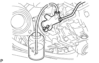
Connect a vinyl tube to the bleeder plug.
Depress the clutch pedal several times, and then loosen the bleeder plug with the pedal depressed.
When fluid no longer comes out, tighten the bleeder plug, and then release the clutch pedal.
Repeat the previous 2 steps until all the air in the fluid is completely bled.
Tighten the bleeder plug.
- Torque:
- 11 N*m{ 112 kgf*cm , 8 ft.*lbf }
Install the bleeder plug cap.
Check that all the air has been bled from the clutch line.
| 17. INSPECT FLUID LEVEL IN THE RESERVOIR |
Check the fluid level and add fluid if necessary.
- Fluid:
- SAE J1703 or FMVSS No. 116 DOT3
- HINT:
- If fluid leaks, tighten or replace the leaking part.
| 18. INSPECT BRAKE FLUID LEAKAGE |
| 19. INSPECT BRAKE PEDAL HEIGHT |
Check the brake pedal height.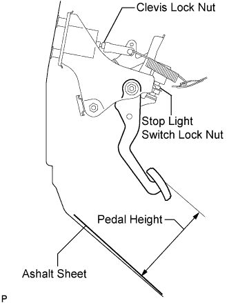
- Pedal height from asphalt sheet (AT for LHD):
- 151.8 to 161.8 mm (5.976 to 6.370 in.)
- Pedal height from asphalt sheet (AT for RHD):
- 147.0 to 157.0 mm (5.787 to 6.181 in.)
- Pedal height from asphalt sheet (MT for LHD):
- 146.6 to 156.6 mm (5.772 to 6.165 in.)
- Pedal height from asphalt sheet (MT for RHD):
- 154.0 to 164.0 mm (6.063 to 6.457 in.)
Adjust brake pedal height.
Disconnect the connector from the stop light switch assembly.
Loosen the stop light switch lock nut. Turn the switch in order to give the pedal some free play.
Remove the brake booster assembly. (Click here)
Loosen the push rod lock nut, turn the push rod clevis and adjust dimension "A" shown in the illustration.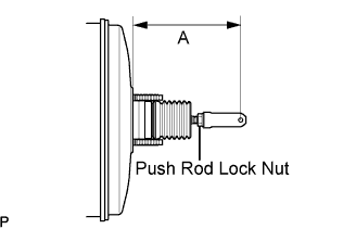
- Dimension "A":
- 146.2 to 147.2 mm (5.756 to 5.795 in.)
Tighten the push rod lock nut.
- Torque:
- 26 N*m{ 265 kgf*cm , 19 ft.*lbf }
Install the brake booster assembly. (Click here)
Turn the stop light switch assembly so that the clearance between the switch and the area where the pedal makes contact is between 0.5 and 2.4 mm (0.020 to 0.095 in.). Tighten the lock nut.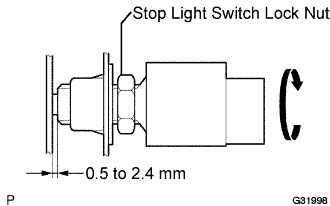
- Torque:
- 17 N*m{ 170 kgf*cm , 12 ft.*lbf }
Connect the connector to the stop light switch assembly.
| 20. INSPECT PEDAL FREE PLAY |
Stop the engine and depress the brake pedal several times until no vacuum is left in the booster.
Press the pedal until a slight resistance is felt. Measure the distance as shown in the illustration.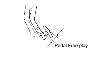
- Pedal free play:
- 1.0 to 2.0 mm (0.039 to 0.079 in.)
- Protrusion of the stop light switch assembly shaft:
- 0.5 to 2.4 mm (0.020 to 0.095 in.)
If the protrusion is within the specified range, it is normal though brake pedal free play is 1.0 mm (0.039 in.) or less.
| 21. INSPECT PEDAL RESERVE DISTANCE |
Release the parking brake pedal.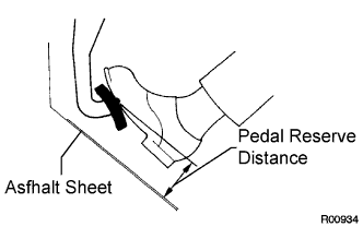
With the engine running, depress the pedal and measure the pedal reserve distance as shown in the illustration.
- Pedal reserve distance from asphalt sheet at 490 N (50 kgf, 110 lbf):
- AT for LHD:
- More than 108 mm (4.25 in.)
- AT for RHD:
- More than 104 mm (4.09 in.)
- MT for LHD:
- More than 104 mm (4.09 in.)
- MT for RHD:
- More than 110 mm (4.33 in.)
| 22. DISCONNECT BATTERY NEGATIVE TERMINAL |
- CAUTION:
- Wait for 90 seconds after disconnecting cable to prevent airbag deployment.
| 23. INSTALL DRIVER SIDE KNEE AIRBAG ASSEMBLY |
| 24. INSTALL LOWER INSTRUMENT PANEL FINISH PANEL SUB-ASSEMBLY |
Connect the connectors.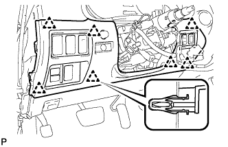
Engage the 7 clips and install the lower instrument panel finish panel sub-assembly.
| 25. INSTALL NO. 1 INSTRUMENT PANEL UNDER COVER SUB-ASSEMBLY |
Connect the connectors.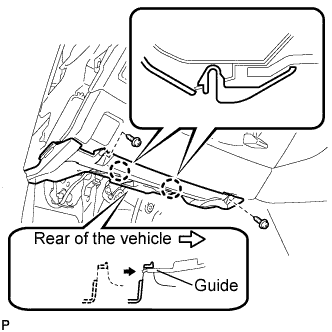
Insert the No. 1 instrument panel under cover sub-assembly into the guide as shown in the illustration.
Engage the 2 claws.
Install the No. 1 instrument panel under cover sub-assembly with the 2 screws <E>.
| 26. INSTALL INSTRUMENT SIDE PANEL LH |
Engage the 5 claws and 3 clips, and then install the side instrument panel LH.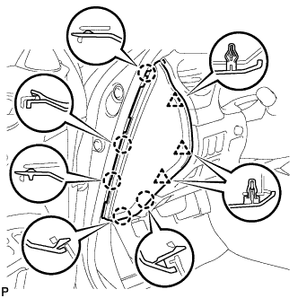
| 27. INSTALL INSTRUMENT SIDE PANEL RH |
Engage the 5 claws and 3 clips, and then install the side instrument panel RH.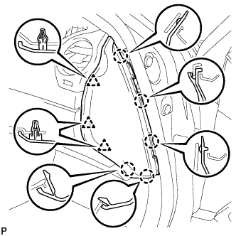
| 28. INSTALL FRONT DOOR OPENING TRIM COVER LH |
Engage the 6 claws and install the front door opening trim cover LH.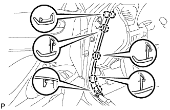
| 29. INSTALL FRONT DOOR OPENING TRIM COVER RH |
Engage the 6 claws and install the front door opening trim cover RH.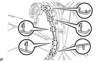
| 30. INSTALL FRONT DOOR SCUFF PLATE LH |
| 31. INSTALL FRONT DOOR SCUFF PLATE RH |
| 32. INSPECT BRAKE ACTUATOR ASSEMBLY |
- HINT:
- (Click here)
| 33. INSTALL FRONT WHEEL |
- Torque:
- 103 N*m{ 1,050 kgf*cm , 76 ft.*lbf }
| 34. INSTALL COWL TOP VENTILATOR LOUVER SUB-ASSEMBLY |
Engage the 11 claws.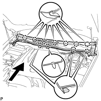
Install the cowl top ventilator louver sub-assembly with the 2 clips.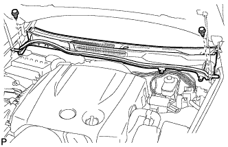
| 35. INSTALL WINDSHIELD WIPER ARM AND BLADE ASSEMBLY RH |
Operate the wiper, and stop the windshield wiper motor at the automatic stop position.
Clean the wiper arm serrations.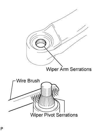
Clean the wiper pivot serrations with a wire brush (when reinstalling).
Install the front wiper arm and blade assembly RH with the nut at the position as shown in the illustration.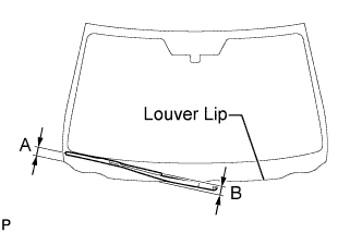
- Torque:
- 22 N*m{ 224 kgf*cm , 16 ft.*lbf }
- HINT:
- Hold the arm hinge by hand to fasten the nut.
Area
Measurement
A
18.5 to 33.5 mm (0.73 to 1.32 in.)
B
Approx. 20 mm (0.79 in.)
Operate the front wipers while spraying washer fluid on the windshield glass. Make sure that the front wipers function properly and there is no interference with the vehicle body.
| 36. INSTALL WINDSHIELD WIPER ARM AND BLADE ASSEMBLY LH |
Operate the wiper, and stop the windshield wiper motor at the automatic stop position.
Clean the wiper arm serrations.
Clean the wiper pivot serrations with a wire brush (when reinstalling).
Install the front wiper arm and blade assembly LH with the nut at the position as shown in the illustration.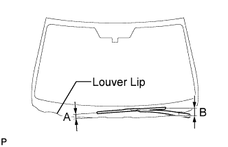
- Torque:
- 22 N*m{ 224 kgf*cm , 16 ft.*lbf }
- HINT:
- Hold the arm hinge by hand to fasten the nut.
Area
Measurement
A
15 to 30 mm (0.59 to 1.18 in.)
B
Approx. 40 mm (1.57 in.)
| 37. INSTALL FRONT WIPER ARM HEAD CAP |
Install the front wiper arm head cap.
- HINT:
- Use the same procedures for the RH side and the LH side.
| 38. INSTALL ROOF DRIP SIDE FINISH MOULDING RH |
| 39. INSTALL ROOF DRIP SIDE FINISH MOULDING LH |
| 40. INSTALL FRONT UPPER FENDER PROTECTOR RH |
- HINT:
- Use the same procedures for the RH side and the LH side.
| 41. INSTALL FRONT UPPER FENDER PROTECTOR LH |
Engage the claw and the 3 clips, then install the front upper fender protector LH.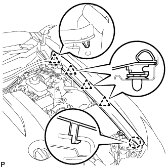
Engage the clip on the rubber portion of the cowl top ventilator louver sub-assembly to the front fender protector upper LH.
| 42. INSTALL ENGINE ROOM SIDE COVER RH |
Install the side cover with the 2 clips.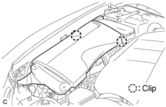
| 43. INSTALL ENGINE ROOM SIDE COVER LH |
Install the side cover with the 5 clips.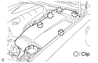
| 44. INSTALL COOL AIR INTAKE DUCT SEAL |
Install the intake duct seal with the 11 clips.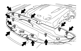
| 45. CONNECT BATTERY NEGATIVE TERMINAL |
| 46. INSPECT VSC SENSOR SIGNAL |
Inspect the VSC sensor signal (Click here).
| 47. INSPECT SRS WARNING LIGHT |
- HINT:
- (Click here)
| 48. PERFORM INITIALIZATION |