B2415
Diagnostic trouble codes
DESCRIPTION
The AFS ECU receives signals regarding the front wheel speed from the skid control ECU.| DTC No. |
DTC Condition Condition |
Trouble Area |
| B2415 |
|
|
WIRING DIAGRAM
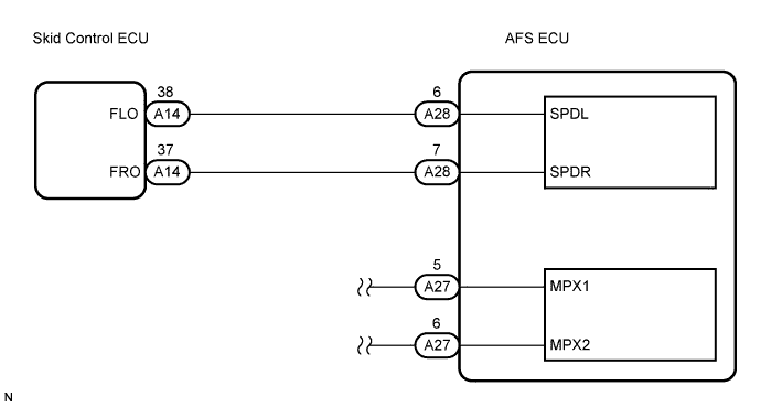

INSPECTION PROCEDURE
| 1. CHECK DTC (VEHICLE STABILITY CONTROL SYSTEM) |

Check that no DTC for vehicle stability control system (Click here).
- Result:
Result
Proceed to
DTC is not output
A
DTC is output
B
|
|
||||

| A | |
 |
| 2. CHECK HARNESS AND CONNECTOR (SKID CONTROL ECU WITH ACTUATOR) |
Disconnect the A14 skid control ECU with actuator connector.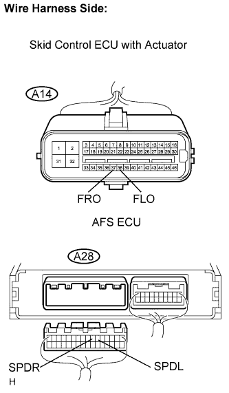
Disconnect the A28 AFS ECU connector.
Measure the resistance according to the value(s) in the table below.
- Standard resistance:
Tester Connection
Condition
Specified Condition
A14-37 (FRO) - A28-7 (SPDR)
Always
Below 1 Ω
A14-38 (FLO) - A28-6 (SPDL)
Always
Below 1 Ω
A28-7 (SPDR) - Body ground
Always
10 kΩ or higher
A28-6 (SPDL) - Body ground
Always
10 kΩ or higher
|
|
||||
| OK | |
|
| 3. CHECK AFS ECU |
Disconnect the A28 AFS ECU connector.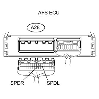
Measure the voltage of the connector.
- Standard voltage:
Tester Connection
Condition
Specified Voltage
A28-6 (SPDL) - Body ground
Vehicle is driving at approx. 30 km/h (19 mph)
0 to 5 V
Pulse generation (see waveform 1)
A28-7 (SPDR) - Body ground
Vehicle is driving at approx. 30 km/h (19 mph)
0 to 5 V
Pulse generation (see waveform 1)
Waveform 1: Oscilloscope wave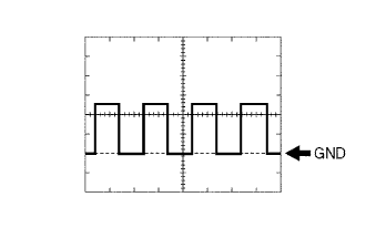
Item
Contents
Tool setting
2 V/DIV., 2 ms./DIV.
Vehicle condition
Vehicle is driving at approximately 30 km/h (19 mph)
- OK:
- Waveform is output as shown in the illustration.
- Result:
Result
Proceed to
OK (When checking from DIAGNOSTICS TROUBLE CODE CHART)
A
OK (When checking from PROBLEM SYMPTOMS TABLE)
B
NG
B
|
|
||||
|
|
||||
| A | ||
 |
||
| ||