B2416
Diagnostic trouble codes
DESCRIPTION
The AFS ECU receives signals regarding the height of the front/rear of the vehicle from the height control sensor.| DTC No. |
DTC Detection Condition |
Trouble Area |
| B2416 |
|
|
WIRING DIAGRAM
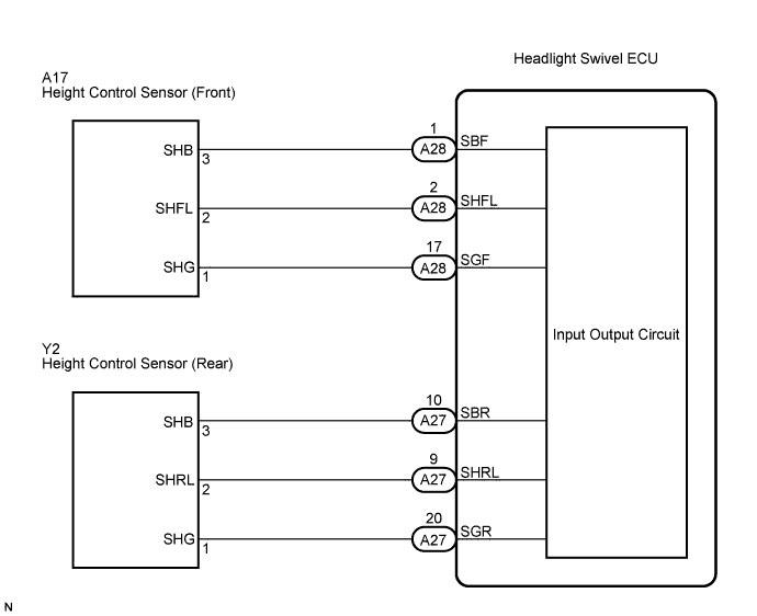

INSPECTION PROCEDURE
| 1. READ VALUE OF INTELLIGENT TESTER |

Connect the intelligent tester to the DLC3.
Turn the engine switch on (IG).
Turn the intelligent tester main switch on.
Select the "DATA LIST" on the intelligent tester, and read the displays on the intelligent tester.
DATA LIST: AFS ECU Item
Measurement Item / Display (Range)
Normal Condition
Diagnostic Note
Fr Height Sens
Front height sensor signal value / 0 to 5 V
Approx. 2.5 V
-
Rr Height Sens
Rear height sensor signal value / 0 to 5 V
Approx. 2.5 V
-
- OK:
- Condition sign can be displayed.
- Result:
Result
Proceed to
OK (When checking from PROBLEM SYMPTOMS TABLE)
A
OK (When checking from DIAGNOSTIC TROUBLE CODE CHART)
B
NG
C
|
|
||||
|
|
||||


| A | ||
 |
||
| ||
| 2. CHECK HARNESS AND CONNECTOR (FRONT HEIGHT CONTROL SENSOR CIRCUIT) |
Disconnect the A17 front height control sensor connector.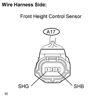
Measure the voltage according to the value(s) in the table below.
- Standard voltage:
Tester Connection
Condition
Specified Condition
A17-1 (SHG) - A17-3 (SHB)
Engine switch on (IG)
4.5 to 5.5 V
|
|
||||
| OK | |
 |
| 3. CHECK HARNESS AND CONNECTOR (REAR HEIGHT CONTROL SENSOR CIRCUIT) |
Disconnect the Y2 rear height control sensor connector.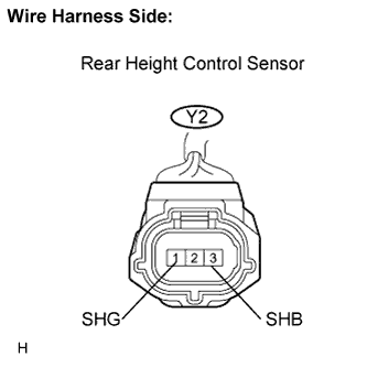
Measure the voltage according to the value(s) in the table below.
- Standard voltage:
Tester Connection
Condition
Specified Condition
Y2-1 (SHG) - Y2-3 (SHB)
Engine switch on (IG)
4.5 to 5.5 V
|
|
||||
| OK | |
|
| 4. CHECK HARNESS AND CONNECTOR (AFS ECU - FRONT HEIGHT CONTROL SENSOR) |
Disconnect the A28 AFS ECU connector.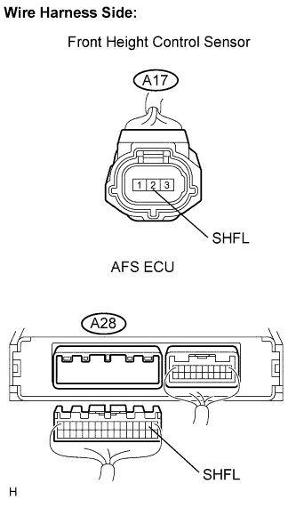
Measure the resistance according to the value(s) in the table below.
- Standard resistance:
Tester Connection
Condition
Specified Condition
A28-2 (SHFL) - A17-2 (SHFL)
Always
Below 1 Ω
A28-2 (SHFL) - Body ground
Always
10 kΩ or higher
|
|
||||
| OK | |
|
| 5. CHECK HARNESS AND CONNECTOR (AFS ECU - REAR HEIGHT CONTROL SENSOR) |
Disconnect the Y2 sensor connector.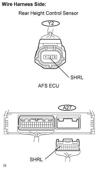
Disconnect the A27 AFS ECU connector.
Measure the resistance of the wire harness side connectors.
- Standard resistance:
Tester Connection
Condition
Specified Condition
A27-9 (SHRL) - Y2-2 (SHRL)
Always
Below 1 Ω
A27-9 (SHRL) - Body ground
Always
10 kΩ or higher
|
|
||||
| OK | |
|
| 6. INSPECT HEIGHT CONTROL SENSOR (FRONT HEIGHT CONTROL SENSOR) |
Connect the 3 dry cell batteries (1.5 V) in series.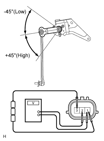
Remove the height control sensor assembly front.
Connect the positive (+) lead from the battery to terminal 3 and the negative (-) lead from the battery to terminal 1.
Measure the voltage between terminals 2 and 1 while slowly moving the link up and down.
- Standard voltage:
Tester Connection
Condition
Specified Condition
A17-2 (SHFL) - A17-1 (SHG)
+45°
Approx. 4.5 V
A17-2 (SHFL) - A17-1 (SHG)
0° (Normal)
Approx. 2.5 V
A17-2 (SHFL) - A17-1 (SHG)
-45° (Low)
Approx. 0.5 V
|
|
||||
| OK | |
|
| 7. INSPECT HEIGHT CONTROL SENSOR (REAR HEIGHT CONTROL SENSOR) |
Connect the 3 dry cell batteries (1.5 V) in series.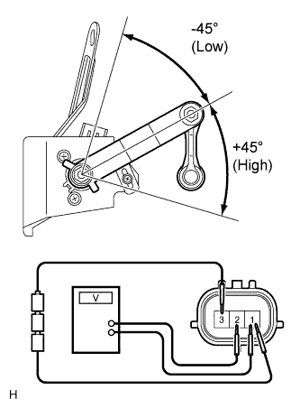
Remove the height control sensor assembly rear.
Connect the positive (+) lead from the battery to terminal 3 and the negative (-) lead from the battery to terminal 1.
Measure the voltage between terminals 2 and 1 while slowly moving the link up and down.
- Standard voltage:
Tester Connection
Condition
Specified Condition
Y2-2 (SHRL) - Y2-1 (SHG)
+45°
Approx. 4.5 V
Y2-2 (SHRL) - Y2-1 (SHG)
0° (Normal)
Approx. 2.5 V
Y2-2 (SHRL) - Y2-1 (SHG)
-45° (Low)
Approx. 0.5 V
|
|
||||
| OK | ||
|
||
| ||
| 8. CHECK HARNESS AND CONNECTOR (AFS ECU - FRONT HEIGHT CONTROL SENSOR) |
Disconnect the A17 front height control sensor connector.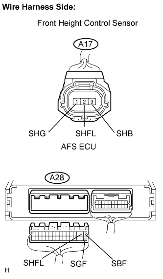
Disconnect the A28 AFS ECU connector.
Measure the resistance according to the value(s) in the table below.
- Standard resistance:
Tester Connection
Condition
Specified Condition
A28-1 (SBF) - A17-3 (SHB)
Always
Below 1 Ω
A28-2 (SHFL) - A17-2 (SHFL)
Always
Below 1 Ω
A28-17 (SGF) - A17-1 (SHG)
Always
Below 1 Ω
A28-1 (SBF) - Body ground
Always
10 kΩ or higher
A28-2 (SHFL) - Body ground
Always
10 kΩ or higher
A28-17 (SGF) - Body ground
Always
10 kΩ or higher
|
|
||||
| OK | ||
|
||
| ||
| 9. CHECK HARNESS AND CONNECTOR (AFS ECU - REAR HEIGHT CONTROL SENSOR) |
Disconnect the Y2 sensor connector.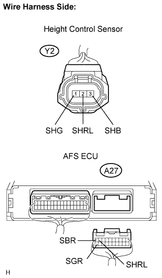
Disconnect the A27 AFS ECU connector.
Measure the resistance of the wire harness side connectors.
- Standard resistance:
Tester Connection
Condition
Specified Condition
A27-10 (SBR) - Y2-3 (SHB)
Always
Below 1 Ω
A27-9 (SHRL) - Y2-2 (SHFL)
Always
Below 1 Ω
A27-20 (SGR) - Y2-1 (SHG)
Always
Below 1 Ω
A27-10 (SBR) - Body ground
Always
10 kΩ or higher
A27-9 (SHRL) - Body ground
Always
10 kΩ or higher
A27-20 (SGR) - Body ground
Always
10 kΩ or higher
|
|
||||
| OK | ||
|
||
| ||