REMOVAL
Removal / installation
| 1. PRECAUTION |

- CAUTION:
- Be sure to read the "PRECAUTION" thoroughly before servicing (Click here).
| 2. DISCONNECT CABLE FROM NEGATIVE BATTERY TERMINAL |
- CAUTION:
- Wait for 90 seconds after disconnecting the cable to prevent the airbag working.
| 3. REMOVE FRONT SEAT ASSEMBLY (for Power Seat) |
- HINT:
- (Click here)
| 4. REMOVE FRONT SEAT ASSEMBLY (for Manual Seat) |
- HINT:
- (Click here)
| 5. REMOVE REAR SEAT CUSHION ASSEMBLY |
Detach the 2 front hooks of the seat cushion from the vehicle body.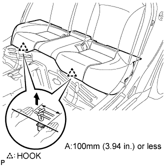

- NOTICE:
- Follow the instructions below carefully as the cushion frame deforms easily.
Choose a hook to detach first. Place your hands near the hook as shown in the illustration. Then lift the seat cushion to detach the hook.
Repeat for the other hook.
Detach the 2 rear hooks of the seat cushion from the seatback.
Remove the seat cushion.
| 6. DISCONNECT FRONT SEAT OUTER BELT ASSEMBLY |
Remove the bolt and disconnect the floor end of the front seat outer belt assembly.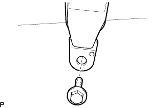
| 7. REMOVE FRONT DOOR SCUFF PLATE LH (w/o Illumination) |
Put protective tape around the front door scuff plate.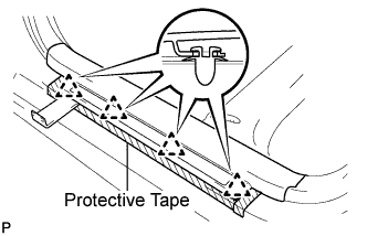
Using a moulding remover, disengage the 4 clips.
Disengage the 7 claws and remove the front door scuff plate LH.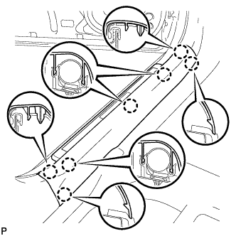
| 8. REMOVE FRONT DOOR SCUFF PLATE LH (w/ Illumination) |
Put protective tape around the front door scuff plate.
Using a moulding remover, disengage the 4 clips.
Disengage the 7 claws and remove the front door scuff plate LH.
Disconnect the connector.
| 9. REMOVE REAR DOOR SCUFF PLATE LH |
Put protective tape around the rear door scuff plate.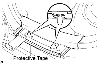
Using a moulding remover, disengage the 2 clips.
Disengage the 5 claws and remove the the rear door scuff plate LH.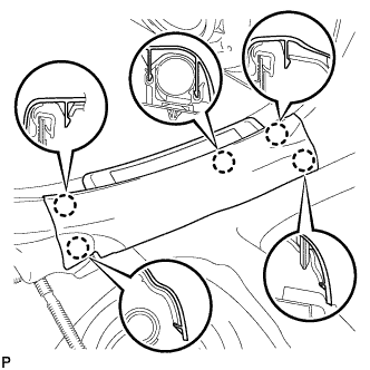
| 10. REMOVE CENTER LOWER PILLAR GARNISH LH |
Disengage the 3 claws and 5 clips, and remove the lower center pillar garnish LH.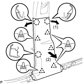
| 11. REMOVE FRONT DOOR OPENING TRIM COVER LH |
Disengage the 4 claws and remove the front door opening trim cover LH.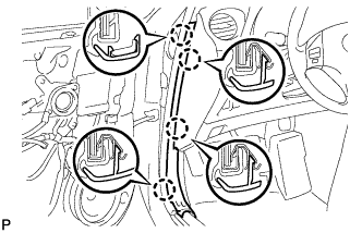
| 12. REMOVE SHIFT LEVER KNOB SUB-ASSEMBLY |
Turn the shift lever knob counterclockwise and remove the shift lever knob sub-assembly.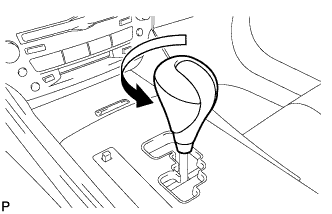
| 13. REMOVE NO. 1 UPPER CONSOLE PANEL GARNISH |
Using a moulding remover, disengage the claw.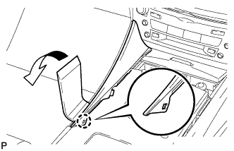
Pull the upper No. 1 console panel garnish in the direction indicated by the arrow to disengage the 2 clips and remove it.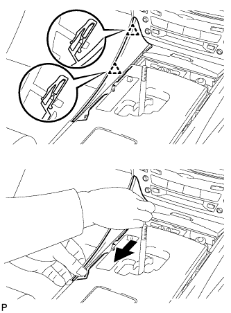
| 14. REMOVE NO. 2 UPPER CONSOLE PANEL GARNISH |
Using a moulding remover, disengage the claw.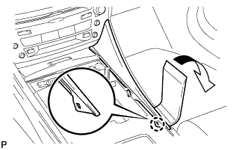
Pull the upper No. 2 console panel garnish in the direction indicated by the arrow to disengage the 2 clips and remove it.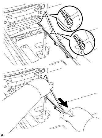
| 15. REMOVE CONSOLE PANEL SUB-ASSEMBLY |
Disengage the 8 clips.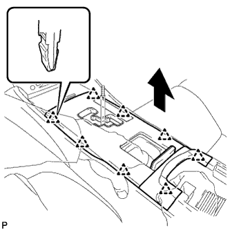
Disconnect the connectors and remove the console panel sub-assembly.
| 16. REMOVE FRONT ASH RECEPTACLE ASSEMBLY |
Remove the 2 screws <F>.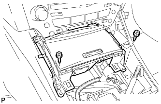
Pull the front ash receptacle sub-assembly in the direction indicated by the arrow to disconnect the connectors and remove it.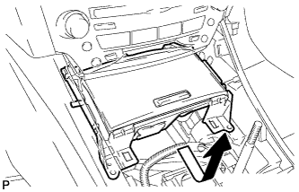
| 17. REMOVE CONSOLE BOX REGISTER ASSEMBLY |
Remove the rear ash receptacle assembly.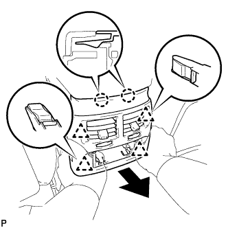
Disengage the 2 claws and 4 clips, and then remove the console box register assembly.
| 18. REMOVE CONSOLE BOX |
Remove the 2 bolts <C>.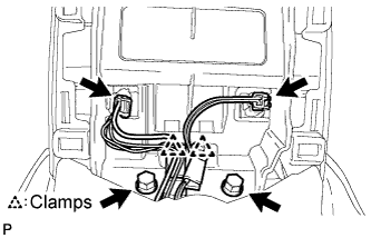
Disconnect the 2 connectors.
Disengage the 2 clamps.
Remove the 2 bolts <C>.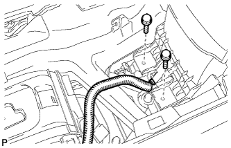
Disconnect the connector.
Remove the 2 bolts <C>.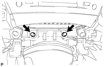
Disengage the 2 claws and 2 clips, and then remove the console box.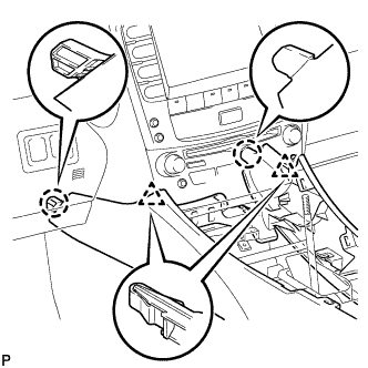
| 19. REMOVE SIDE INSTRUMENT PANEL LH |
Using a moulding remover, disengage the 5 claws and 3 clips, and then remove the side instrument panel LH.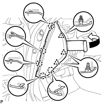
| 20. REMOVE NO. 1 INSTRUMENT PANEL UNDER COVER SUB-ASSEMBLY |
Remove the 2 screws <E>.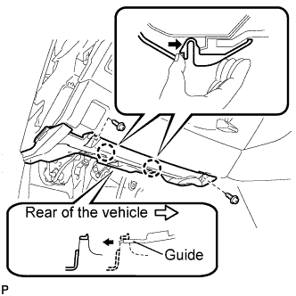
Push the 2 claws in the direction indicated by the arrow to disengage them.
Remove the No. 1 instrument panel under cover sub-assembly from the guide as shown in the illustration and pull the cover toward the rear of the vehicle.
Disconnect the connectors and remove the No. 1 instrument panel under cover sub-assembly.
| 21. REMOVE LOWER INSTRUMENT FINISH PANEL SUB-ASSEMBLY |
Disengage the 7 clips.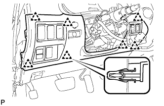
Disconnect the connectors and remove the lower instrument panel finish panel sub-assembly.
| 22. REMOVE DRIVER SIDE KNEE AIRBAG ASSEMBLY |
Remove the 4 bolts and driver side knee airbag assembly.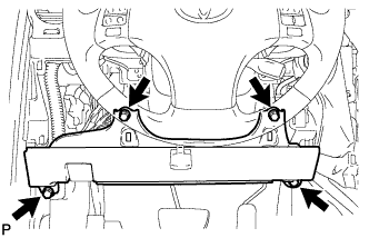
Disconnect the connector.
- NOTICE:
- When handling the airbag connector, take care not to damage the airbag wire harness.
| 23. REMOVE ACCELERATOR PEDAL |
- HINT:
- (Click here).
| 24. REMOVE FRONT FLOOR SILENCER PAD |
Remove the front floor silencer pad.
| 25. REMOVE NO. 2 REAR AIR DUCT |
Remove the 2 clips and the No. 2 rear air duct.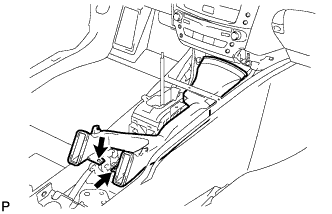
| 26. REMOVE PROPELLER SHAFT WITH CENTER BEARING ASSEMBLY |
- HINT:
- Refer to the procedures up to "REMOVE PROPELLER SHAFT ASSEMBLY" (Click here).
| 27. REMOVE NO. 3 DASH PANEL INSULATOR PAD |
| 28. REMOVE CENTER AIRBAG SENSOR ASSEMBLY |
Disconnect the holder (with connectors).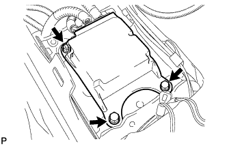
Remove the nut, 2 bolts and center airbag sensor assembly.
| 29. REMOVE FRONT UPPER FLOOR REAR SUB PANEL |
Turn back the floor carpet in order to remove the front floor rear upper sub panel.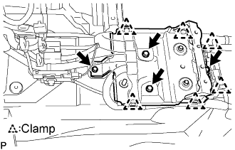
Disengage the 6 clamps.
Remove the 4 bolts and front floor rear upper sub panel.
| 30. REMOVE NO. 1 AIR DUCT (for RHD) |
Disengage the claw and remove the No. 1 air duct.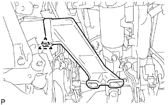
| 31. REMOVE PARKING BRAKE PEDAL ASSEMBLY (for LHD) |
Remove the parking brake return with damper spring.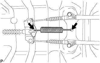
Remove the 2 bolts and separate the 2 No. 2 parking brake cable assemblies from the parking brake equalizer.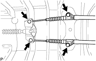
Slide the rubber boot as shown in the illustration.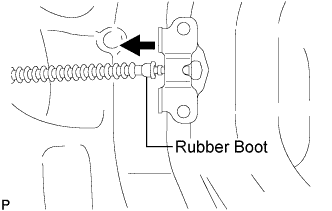
Remove the parking brake equalizer from the No. 1 parking brake cable assembly.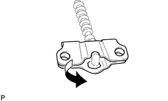
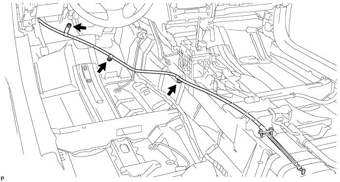
Remove the 2 bolts and 3 nuts, and separate the No. 1 parking brake cable assembly from the body.
Remove the 2 nuts and separate the instrument panel junction block assembly.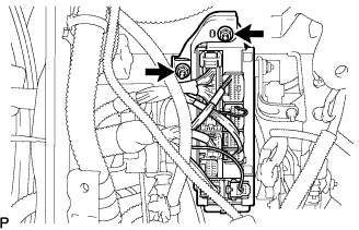
Disconnect the parking brake switch connector.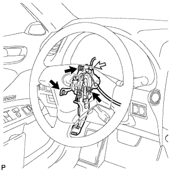
Remove the 3 nuts and parking brake pedal from the body.
Pull up the parking brake pedal claw.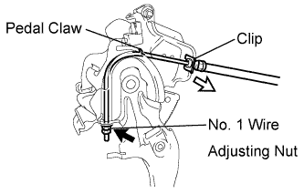
Remove the lock nut and No. 1 wire adjusting nut of the No. 1 parking brake cable assembly from the parking brake pedal.
Remove the clip and No. 1 parking brake cable assembly from the parking brake pedal.
| 32. REMOVE PARKING BRAKE PEDAL ASSEMBLY (for RHD) |
Remove the parking brake return with damper spring.
Remove the 2 bolts and separate the No. 2 parking brake cable assembles from the parking brake equalizer.
Slide the rubber boot as shown in the illustration.
Remove the parking brake equalizer from the No. 1 parking brake cable assembly.
Remove the 2 bolts and 3 nuts, and separate the No. 1 parking brake cable assembly from the body.
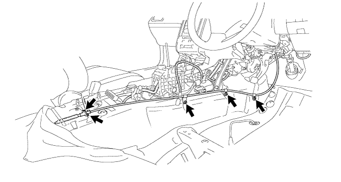
Remove the 2 nuts and separate the instrument panel junction block assembly.
Disconnect the parking brake switch connector.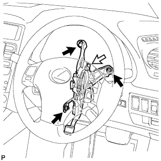
Remove the 2 nuts, bolt and parking brake pedal from the body.
Put up the parking brake pedal claw
Remove the lock nut and No. 1 wire adjusting nut of the No. 1 parking brake cable assembly from the parking brake pedal.
Remove the clip and No. 1 parking brake cable assembly from the parking brake pedal.
| 33. REMOVE PARKING PEDAL PAD |
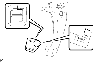
Disengage the claw and remove the perking pedal pad from the parking brake pedal.