INSTALLATION
Removal / installation
| 1. INSTALL LOWER NO. 2 ARM BRACKET ASSEMBLY |

Temporarily install the lower No. 2 arm bracket assembly to the front lower suspension arm with the nut and washer.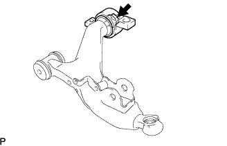

| 2. INSTALL FRONT LOWER BALL JOINT |
Install the front lower ball joint to the front lower suspension arm with the nut.
- NOTICE:
- Ensure that the thread and taper are free of oil or other foreign matter.
- Torque:
- 162 N*m{ 1,650 kgf*cm , 120 ft.*lbf }
Install a new clip to the front lower ball joint.
- NOTICE:
- Further tighten the nut up to 60° if the holes for the cotter pin are not aligned.
| 3. TEMPORARILY TIGHTEN FRONT LOWER SUSPENSION ARM |
Install the front lower suspension arm and side rail plate with the 4 bolts.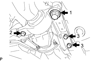
- Torque:
- Bolt 1:
- 204 N*m{ 2,080 kgf*cm , 150 ft.*lbf }
- Bolt 2:
- 86 N*m{ 877 kgf*cm , 63 ft.*lbf }
- Bolt 3:
- 50 N*m{ 510 kgf*cm , 37 ft.*lbf }
Temporarily tighten the bolt, washer, and nut.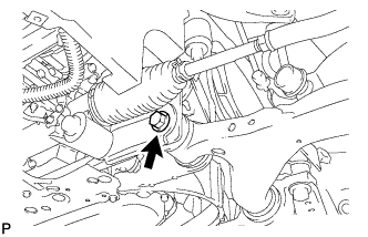
- HINT:
- Insert the bolt from the front of the vehicle.
Install the front lower ball joint with the 2 bolts.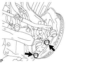
- Torque:
- 120 N*m{ 1,220 kgf*cm , 89 ft.*lbf }
| 4. TEMPORARILY TIGHTEN FRONT SHOCK ABSORBER WITH COIL SPRING |
Insert the bolt from the rear of the vehicle, and install the front shock absorber lower side on the front lower suspension arm.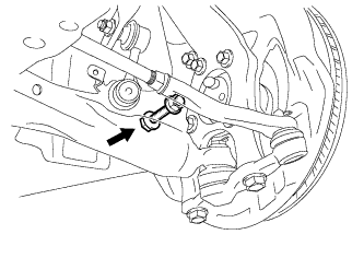
Temporarily tighten a new nut while holding the bolt.
| 5. CONNECT FRONT STABILIZER LINK ASSEMBLY |
Install the front stabilizer link assembly LH with the 2 nuts.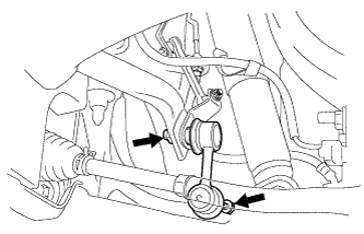
- Torque:
- 84 N*m{ 856 kgf*cm , 62 ft.*lbf }
- HINT:
- If the ball joint turns together with the nut, use a hexagon (6 mm) wrench to hold the stud.
| 6. CONNECT TIE ROD ASSEMBLY |
Connect the tie rod end LH to the steering knuckle with the nut.
- Torque:
- 65 N*m{ 663 kgf*cm , 50 ft.*lbf }
Install a new clip.
- NOTICE:
- If the holes for the clip are not aligned, tighten the nut up to 60° further.
| 7. CONNECT FRONT SPEED SENSOR |
Install the front speed sensor to the front shock absorber with coil spring with the 2 bolts.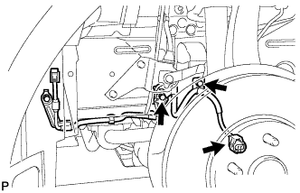
- Torque:
- 6.0 N*m{ 61 kgf*cm , 4.4 ft.*lbf }
- NOTICE:
- Do not twist the front speed sensor while installing it.
- Be careful not to deform the bracket of the front shock absorber with coil spring when installing the bolts.
- Do not twist the front speed sensor while installing it.
| 8. CONNECT HEIGHT CONTROL SENSOR LINK ASSEMBLY FRONT |
Connect the front stabilizer link assembly with the nut.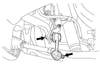
- Torque:
- 5.4 N*m{ 55 kgf*cm , 48 in.*lbf }
| 9. STABILIZE SUSPENSION |
Install the front wheel.
- Torque:
- 103 N*m{ 1,050 kgf*cm , 76 ft.*lbf }
Lower the vehicle and bounce it up and down several times to stabilize the front suspension. Raise the vehicle.
Remove the front wheel.
Jack up the front lower suspension arm placing a wooden block in between. Apply a load to the front suspension so that the front lower suspension arm is placed in a horizontal position.
| 10. FULLY TIGHTEN FRONT SHOCK ABSORBER WITH COIL SPRING |
Fully tighten the bolt on the lower side of the front shock absorber while holding the nut.
- Torque:
- 157 N*m{ 1,600 kgf*cm , 116 ft.*lbf }
| 11. FULLY TIGHTEN FRONT LOWER SUSPENSION ARM |
Fully tighten the bolt on the front of the front lower suspension arm.
- Torque:
- 135 N*m{ 1,380 kgf*cm , 100 ft.*lbf }
Fully tighten the installation nut of the lower No. 2 arm bracket assembly.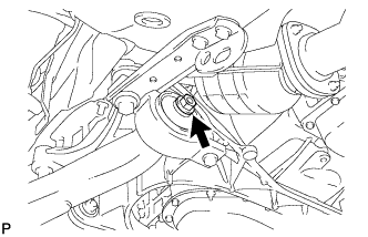
- Torque:
- 113 N*m{ 1,150 kgf*cm , 83 ft.*lbf }
| 12. INSTALL ENGINE UNDER COVER |
| 13. INSTALL FRONT WHEEL |
- Torque:
- 103 N*m{ 1,050 kgf*cm , 76 ft.*lbf }
| 14. INSPECT AND ADJUST FRONT WHEEL ALIGNMENT |