B2284
Diagnostic trouble codes
DESCRIPTION
This DTC is output when: 1) the brake signal circuit between the power source control ECU and the stop light switch is malfunctioning; and 2) the BEAN information is inconsistent.- HINT:
- When the power source control ECU is replaced with a new one and the negative (-) battery terminal is connected, the power source mode becomes the IG-ON mode. When the battery is removed and reinstalled, the power source mode that was selected when the battery was removed is restored.
| DTC No. |
DTC Detection Condition |
Trouble Area |
| B2284 |
Communication or communication line is abnormal between the power source control ECU and the stop light switch |
|
WIRING DIAGRAM
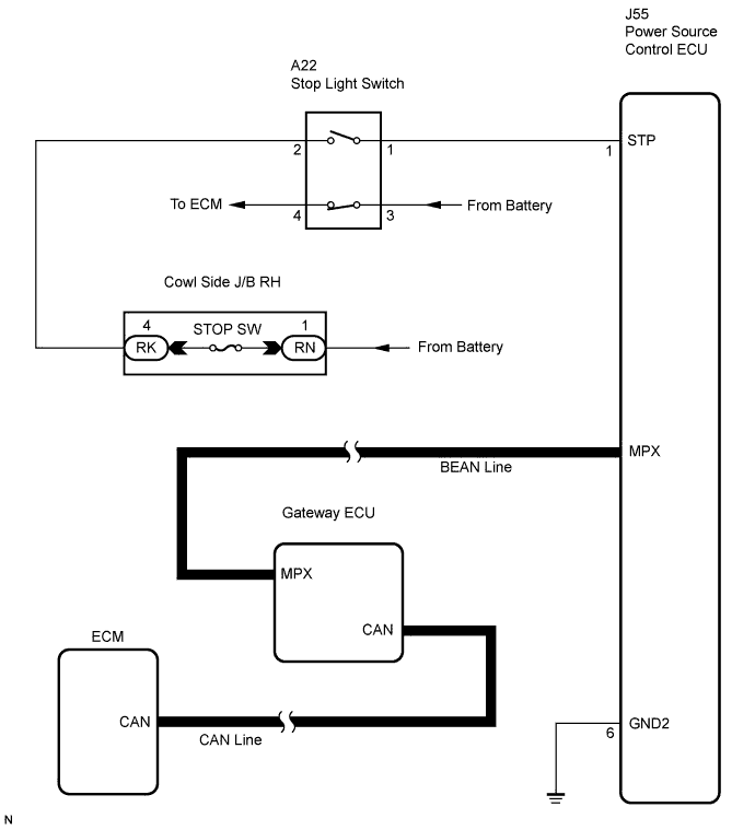

INSPECTION PROCEDURE
- HINT:
- Before performing the inspection, depress the brake pedal and check that the stop lights come on. If the stop lights do not come on when the brake pedal is depressed, refer to the page shown in the brackets (Click here).
| 1. CHECK DTC OUTPUT (MULTIPLEX NETWORK COMMUNICATION SYSTEM) |

Delete the DTC (Click here).
Check for the multiplex network communication system DTCs B1210, B1214 and B1215.
- HINT:
- If the DTCs for the multiplex network communication system malfunction are output, inspect those DTCs first (Click here).
- OK:
- No DTC is output.
|
|
||||

| OK | |
 |
| 2. CHECK DTC OUTPUT (CAN COMMUNICATION SYSTEM) |
Delete the DTC (Click here).
Check for the CAN communication system DTC U0146.
- HINT:
- If the DTCs for the CAN communication system malfunction are output, inspect those DTCs first (LHD: Click here, RHD: Click here).
- OK:
- No DTC is output.
|
|
||||
| OK | |
|
| 3. INSPECT FUSE (STOP SW) |
Remove the STOP SW fuse from the cowl side J/B RH.
Measure the resistance of the fuse.
- Standard resistance:
- Below 1 Ω
|
|
||||
| OK | |
|
| 4. CHECK CONNECTORS |
Check that the connectors are securely connected and the terminals are not deformed or loose.
- OK:
- The connectors are securely connected and the terminals are not deformed or loose.
|
|
||||
| OK | |
|
| 5. CHECK WIRE HARNESS (POWER SOURCE CONTROL ECU - BODY GROUND) |
Disconnect the ECU connector.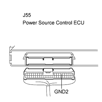
Measure the resistance according to the value(s) in the table below.
- Standard resistance:
Tester Connection (Symbols)
Condition
Specified Condition
J55-6 (GND2) - Body ground
Always
Below 1 Ω
|
|
||||
| OK | |
|
| 6. CHECK WIRE HARNESS (BATTERY - POWER SOURCE CONTROL ECU) |
Measure the volage according to the value(s) in the table below.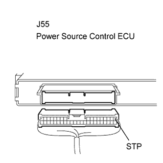
- Standard voltage:
Tester Connection (Symbols)
Condition
Specified Condition
J55-1 (STP) - Body ground
Brake pedal released
Below 1 V
J55-1 (STP) - Body ground
Brake pedal depressed
10 to 14 V
|
|
||||

| NG | |
|
| 7. INSPECT STOP LIGHT SWITCH |
Remove the switch.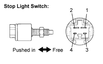
Measure the resistance of the switch.
- Standard resistance:
Tester Connection
Condition
Specified Condition
1 - 2
Switch pin free
Below 1 Ω
3 - 4
Switch pin free
10 kΩ or higher
1 - 2
Switch pin pushed in
10 kΩ or higher
3 - 4
Switch pin pushed in
Below 1 Ω
|
|
||||
| OK | ||
 |
||
| ||
| 8. READ VALUE OF INTELLIGENT TESTER (STOP LIGHT SWITCH) |
Reconnect the connectors.
Check the DATA LIST for proper functioning of the stop light switch.
Power source control ECU: Item
Measurement Item/Display (Range)
Normal Condition
Diagnostic Note
Stop Lamp SW1
Stop light switch 1/ ON or OFF
ON: Brake pedal depressed
OFF: Brake pedal released
-
- OK:
- ON (brake pedal depressed) and OFF (brake pedal released) appear on the screen.
|
|
||||
| OK | ||
|
||
| ||