B2285
Diagnostic trouble codes
DESCRIPTION
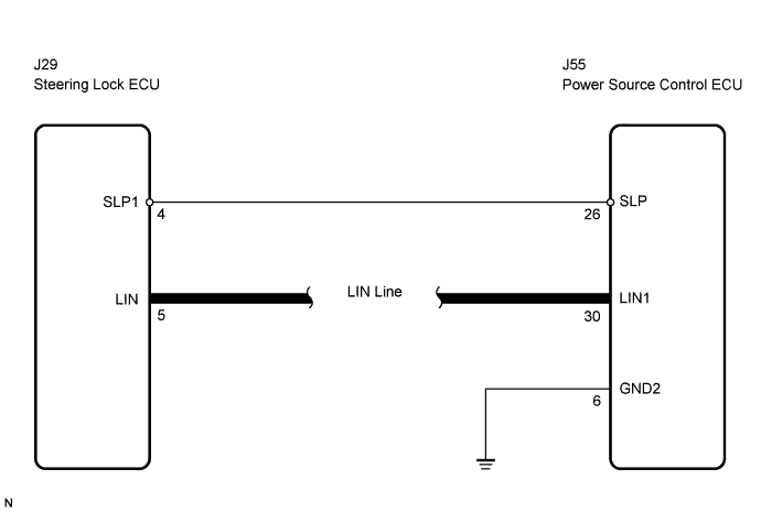
This DTC is output when serial communication signals and LIN communication signals in the circuit between the power source control ECU and steering lock actuator (steering lock ECU) are inconsistent.- HINT:
- When the power source control ECU is replaced with a new one and the negative (-) battery terminal is connected, the power source mode becomes the IG-ON mode. When the battery is removed and reinstalled, the power source mode that was selected when the battery was removed is restored.
| DTC No. |
DTC Detection Condition |
Trouble Area |
| B2285 |
Cable and LIN information between the power source control ECU and the steering lock ECU are inconsistent |
|
WIRING DIAGRAM

INSPECTION PROCEDURE
| 1. CHECK FOR DTCS |

Delete the DTC (Click here).
Check for DTC B2785 and DTC B2287.
- OK:
- DTC B2785 and DTC B2287 are not output.
- HINT:
- IF DTC B2785 is output (Click here).
- IF DTC B2287 is output (Click here).
- IF DTC B2785 is output (Click here).
|
|
||||

| OK | |
 |
| 2. CHECK CONNECTORS |
Check that the connectors are securely connected and the terminals are not deformed or loose.
- OK:
- The connectors are securely connected and the terminals are not deformed or loose.
|
|
||||
| OK | |
|
| 3. CHECK WIRE HARNESS (POWER SOURCE CONTROL ECU - BODY GROUND) |
Disconnect the ECU connector.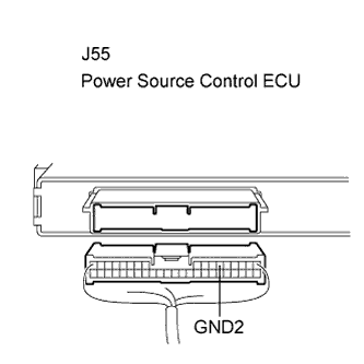
Measure the resistance according to the value(s) in the table below.
- Standard resistance:
Tester Connection (Symbols)
Condition
Specified Condition
J55-6 (GND2) - Body ground
Always
Below 1 Ω
|
|
||||
| OK | |
|
| 4. CHECK WIRE HARNESS (POWER SOURCE CONTROL ECU - STEERING LOCK ECU) |
Disconnect the J29 ECU connector.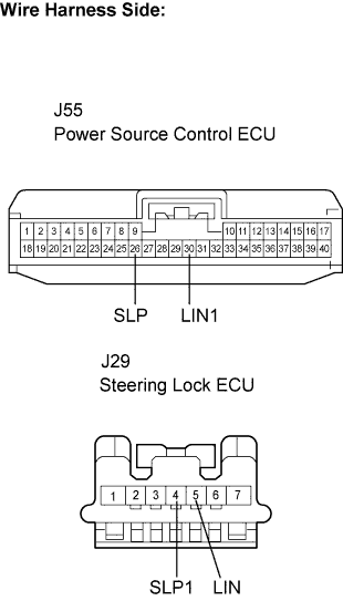
Measure the resistance according to the value(s) in the table below.
- Standard resistance:
Tester Connection (Symbols)
Condition
Specified Condition
J55-26 (SLP) - J29-4 (SLP1)
Always
Below 1 Ω
J55-30 (LIN1) - J29-5 (LIN)
Always
Below 1 Ω
J55-26 (SLP) or J29-4 (SLP1) - Body ground
Always
10 kΩ or higher
J55-30 (LIN1) or J29-5 (LIN) - Body ground
Always
10 kΩ or higher
|
|
||||
| OK | |
|
| 5. INSPECT POWER SOURCE CONTROL ECU |
Reconnect the J55 ECU connector.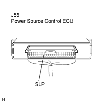
Connect the oscilloscope to the power source control ECU terminals specified in the table below and check the waveform.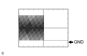
Item
Contents
Terminal (Symbols)
J55-26 (SLP) - Body ground
Equipment Setting
2 V/DIV, 100 ms/DIV
Condition
Engine switch on (IG)
- OK:
- The waveform appears as shown in the illustration.
- HINT:
- The waveform varies depending on the contents of communication.
|
|
||||
| OK | |
|
| 6. INSPECT STEERING LOCK ECU |
Reconnect the J29 ECU connector.
Connect the oscilloscope to the power source control ECU terminals specified in the table below and check the waveform.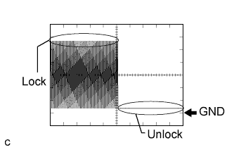
Item
Contents
Terminal (Symbols)
J55-26 (SLP) - Body ground
Equipment Setting
2 V/DIV, 100 ms/DIV
Condition
Steering is LOCK / UNLOCK
- OK:
- The waveform appears as shown in the illustration.
- HINT:
- The waveform varies depending on the contents of communication.
|
|
||||
| OK | ||
 |
||
| ||