C1235/35
Diagnostic trouble codes
DESCRIPTION
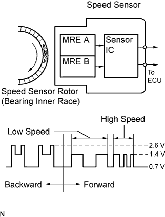
The speed sensor detects wheel speed and sends the appropriate signals to the skid control ECU. These signals are used for the ABS control system. This speed sensor contains a sensor IC, which consists of 2 MREs (Magnetic Resistance Element). The speed sensor rotor, which consists of 48 sets of N and S poles that are arranged in a circle, is integrated with the inner race of the hub bearing.To detect the rotation direction, the output waves are used to determine the relationship of the pulses that are generated by 2 MREs. Upon receiving this signal, the sensor IC outputs a forward or backward wave to the ECU.
DTCs C1275/75 to C1278/78 can be deleted when the speed sensor sends a vehicle speed signal or the Test Mode ends. DTCs C1275/75 to C1278/78 are output only in the Test Mode.

| DTC No. |
DTC Detection Condition |
Trouble Area |
| C1235/35 C1236/36 C1238/38 C1239/39 |
When either of the following is detected:
|
|
- HINT:
- DTC C1235/35 is for the front speed sensor RH.
- DTC C1236/36 is for the front speed sensor LH.
- DTC C1238/38 is for the rear speed sensor RH.
- DTC C1239/39 is for the rear speed sensor LH.
- DTC C1235/35 is for the front speed sensor RH.
WIRING DIAGRAM
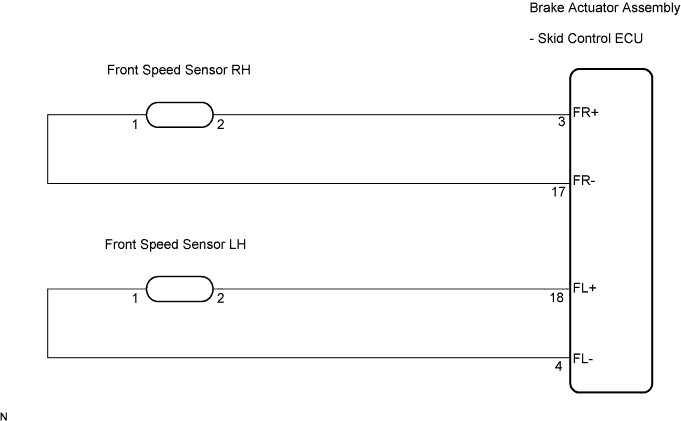
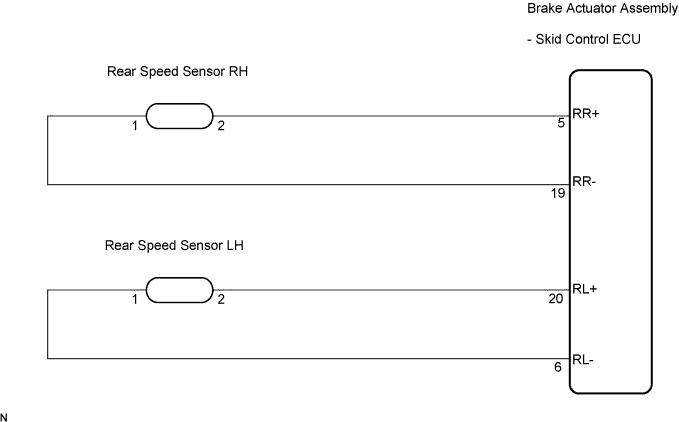
INSPECTION PROCEDURE
- NOTICE:
- When replacing the brake actuator assembly, perform zero point calibration (Click here).
- HINT:
- When C0200/31, C0205/32, C0210/33, or C0215/34 is output together with C1235/35, C1236/36, C1238/38, or C1239/39, inspect and repair the trouble areas indicated by C0200/31, C0205/32, C0210/33, or C0215/34 first.
| 1. CHECK HARNESS AND CONNECTOR (SKID CONTROL ECU - EACH SPEED SENSOR) |

Disconnect the skid control ECU connector and each speed sensor connector.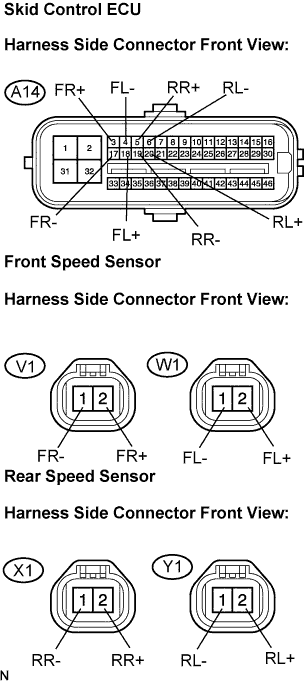
Measure the resistance according to the value(s) in the table below.
- Standard resistance:
- RH:
Tester Connection
Condition
Specified Condition
A14-3 (FR+) - V1-2 (FR+)
Always
Below 1 Ω
A14-3 (FR+) - Body ground
Always
10 kΩ or higher
A14-17 (FR-) - V1-1 (FR-)
Always
Below 1 Ω
A14-17 (FR-) - Body ground
Always
10 kΩ or higher
A14-5 (RR+) - X1-2 (RR+)
Always
Below 1 Ω
A14-5 (RR+) - Body ground
Always
10 kΩ or higher
A14-19 (RR-) - X1-1 (RR-)
Always
Below 1 Ω
A14-19 (RR-) - Body ground
Always
10 kΩ or higher
- LH:
Tester Connection
Condition
Specified Condition
A14-18 (FL+) - W1-2 (FL+)
Always
Below 1 Ω
A14-18 (FL+) - Body ground
Always
10 kΩ or higher
A14-4 (FL-) - W1-1 (FL-)
Always
Below 1 Ω
A14-4 (FL-) - Body ground
Always
10 kΩ or higher
A14-20 (RL+) - Y1-2 (RL+)
Always
Below 1 Ω
A14-20 (RL+) - Body ground
Always
10 kΩ or higher
A14-6 (RL-) - Y1-1 (RL-)
Always
Below 1 Ω
A14-6 (RL-) - Body ground
Always
10 kΩ or higher
|
|
||||

| OK | |
 |
| 2. INSPECT SKID CONTROL ECU (SENSOR INPUT) |
Reconnect the skid control ECU connector.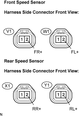
Turn the engine switch on (IG).
Measure the voltage according to the value(s) in the table below.
- Standard voltage:
- RH:
Tester Connection
Condition
Specified Condition
V1-2 (FR+) - Body ground
Engine switch on (IG)
7.5 to 14 V
X1-2 (RR+) - Body ground
Engine switch on (IG)
7.5 to 14 V
- LH:
Tester Connection
Condition
Specified Condition
W1-2 (FL+) - Body ground
Engine switch on (IG)
7.5 to 14 V
Y1-2 (RL+) - Body ground
Engine switch on (IG)
7.5 to 14 V
|
|
||||
| OK | |
|
| 3. RECONFIRM DTC |
Turn the engine switch off.
Reconnect the speed sensor connector.
Clear the DTC (Click here).
Start the engine.
Drive the vehicle at the speed of 12 mph (20 km/h) or more for at least 60 seconds.
Check if the same DTC is recorded (Click here).
- Result:
Condition
Proceed to
DTCs (C1235/35, C1236/36, C1238/38 and/or C1239/39) are output (for rear)
A
DTCs (C1235/35, C1236/36, C1238/38 and/or C1239/39) are output (for front)
B
DTCs (C1235/35, C1236/36, C1238/38 and/or C1239/39) are not output
C
|
|
||||
|
|
||||

| A | |
|
| 4. CHECK REAR SPEED SENSOR TIP |
Turn the engine switch off.
Remove the rear speed sensor (Click here).
Check the speed sensor tip.
- OK:
- No scratches or foreign matter on the sensor tip.
- NOTICE:
- Check the speed sensor signal after cleaning/replacement (Click here).
|
|
||||
| OK | |
|
| 5. CHECK EACH SPEED SENSOR ROTOR |
Turn the engine switch off.
Remove each speed sensor rotor.
Check the speed sensor rotor.
- OK:
- No scratches, oil, or foreign matter on the rotors.
- NOTICE:
- Check the speed sensor signal after cleaning/replacement (Click here).
|
|
||||
| OK | |
|
| 6. RECONFIRM DTC |
Install the speed sensor and the speed sensor rotor.
Clear the DTC (Click here).
Start the engine.
Drive the vehicle at the speed of 12 mph (20 km/h) or more for at least 60 seconds.
Check if the same DTC is recorded (Click here).
- Result:
Condition
Proceed to
DTCs (C1235/35, C1236/36, C1238/38 and/or C1239/39) are output
A
DTCs (C1235/35, C1236/36, C1238/38 and/or C1239/39) are not output
B
|
|
||||
| A | |
|
| 7. REPLACE EACH SPEED SENSOR |
Turn the engine switch off.
Replace each speed sensor (Click here for front, or Click here for rear).
- NOTICE:
- Check the speed sensor signal after replacement (Click here).
| NEXT | |
|
| 8. RECONFIRM DTC |
Clear the DTC (Click here).
Start the engine.
Drive the vehicle at the speed of 12 mph (20 km/h) or more for at least 60 seconds.
Check if the same DTC is recorded (Click here).
- Result:
Condition
Proceed to
DTCs (C1235/35, C1236/36, C1238/38 and/or C1239/39) are output
A
DTCs (C1235/35, C1236/36, C1238/38 and/or C1239/39) are not output
B
|
|
||||
| A | ||
 |
||
| ||