C1232/32
Diagnostic trouble codes
DESCRIPTION
The skid control ECU receives signals from the yaw rate and acceleration sensor via the CAN communication system.The yaw rate sensor has a built in acceleration sensor and detects the vehicle's condition using 2 circuits (GL1, GL2).
If there is trouble in the bus lines between the yaw rate and acceleration sensor and the CAN communication system, the DTC U0123/62 (malfunction in CAN communication with the yaw rate sensor) and U0124/95 (malfunction in CAN communication with the acceleration sensor) are output.
These DTCs are also output when the calibration has not been completed.
DTCs C0371/71 and C1279/79 can be deleted when the yaw rate and acceleration sensor sends a yaw rate and/or acceleration signal or the Test Mode ends. DTCs C0371/71 and C1279/79 are output only in the Test Mode.
| DTC No. |
DTC Detection Condition |
Trouble Area |
| C1232/32 |
At a vehicle speed of 6 mph (10 km/h) or more, either GL1 or GL2 (input signal) does not change for 30 seconds or more. |
|
| C1234/34 |
Sensor malfunction signal is received from the yaw rate sensor. |
|
| C1243/43 |
While the vehicle speed changes from 19 mph (30 km/h) to 0 mph (0 km/h), the condition that the values of GL1 and GL2 do not change occurs 16 times or more. |
|
| C1244/44 |
When either of the following is detected:
|
|
| C1245/45 |
At a vehicle speed of 19 mph (30 km/h) or more, the difference between the forward and backward G calculated from the acceleration sensor value and that calculated from the vehicle speed sensor exceeds 0.35 G for 60 seconds or more. |
|
| C1381/97 |
At a vehicle speed of more than 2 mph (3 km/h), the acceleration sensor power source malfunction signal is received for 10 seconds or more. |
|
WIRING DIAGRAM
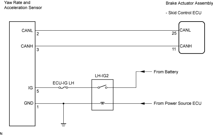

INSPECTION PROCEDURE
- NOTICE:
- When replacing the yaw rate and acceleration sensor, perform zero point calibration (Click here).
- HINT:
- When U0123/62, U0124/95 or U0126/63 is output together with C1232/32, C1234/34, C1243/43, C1244/44, C1245/45, or C1381/97, inspect and repair the trouble areas indicated by U0123/62, U0124/95 or U0126/63 first.
| 1. CHECK DTC |

Clear the DTC (Click here).
Turn the engine switch off.
At a speed of 18 mph (30 km/h) or more, drive the vehicle, turn the steering wheel, and decelerate (depress the brake pedal).
Turn the engine switch on (IG) again and check that no CAN communication system DTC is output.
Check if DTCs for zero point calibration of the yaw rate sensor undone (C1210/36) or for zero point calibration of the acceleration sensor undone (C1336/39) are output.
- Result:
Condition
Proceed to
DTCs (C1210/36, C1336/39, and/or CAN communication system DTC) are not output
A
CAN communication system DTC is output
B
DTCs (C1210/36 and/or C1336/39) are output
C (Click here)
|
|
||||
|
|
||||

| A | |
 |
| 2. CHECK YAW RATE AND ACCELERATION SENSOR INSTALLATION |
Turn the engine switch off.
Check that the yaw rate and acceleration sensor has been installed properly (Click here).
- OK:
- The sensor is tightened to the specified torque.
- The sensor is not tilted.
|
|
||||
| OK | |
|
| 3. INSPECT YAW RATE AND ACCELERATION SENSOR (IG TERMINAL) |
Disconnect the yaw rate and acceleration sensor connector.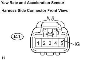
Turn the engine switch on (IG).
Measure the voltage according to the value(s) in the table below.
- Standard voltage:
Tester Connection
Condition
Specified Condition
J41-5 (IG) - Body ground
Engine switch on (IG)
10 to 14 V
|
|
||||
| OK | |
|
| 4. INSPECT YAW RATE AND ACCELERATION SENSOR (GND TERMINAL) |
Turn the engine switch off.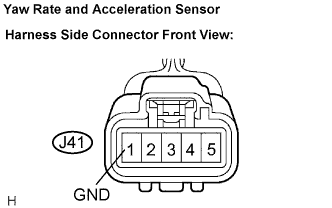
Measure the resistance according to the value(s) in the table below.
- Standard resistance:
Tester Connection
Condition
Specified Condition
J41-1 (GND) - Body ground
Always
Below 1 Ω
- NOTICE:
- Check the yaw rate and acceleration sensor signal after replacement (Click here).
- HINT:
- If troubleshooting has been carried out according to the Problem Symptoms Table, refer back to the table and proceed to the next step (Click here).
|
|
||||
| OK | ||
 |
||
| ||