Illumination Circuit
Circuit diagnosis
DESCRIPTION
Power is supplied to the multi-display and steering pad switch assembly illumination when the light control switch is in the TAIL or HEAD position.WIRING DIAGRAM
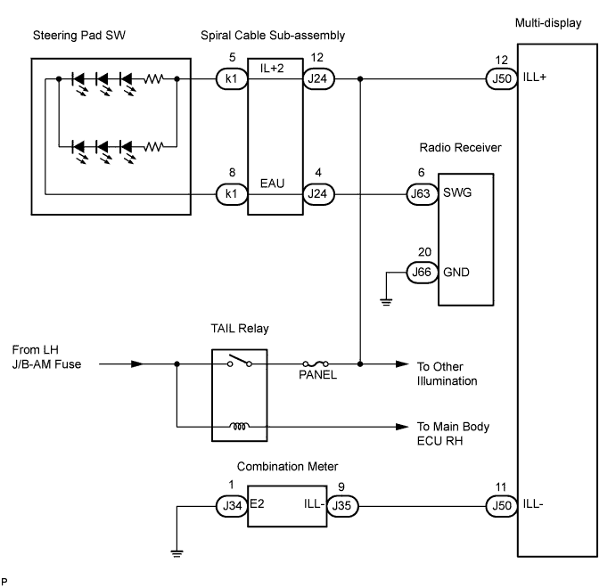

INSPECTION PROCEDURE
- NOTICE:
- The vehicle is equipped with an SRS (Supplemental Restraint System) which includes components such as airbags. Before servicing (including removal or installation of parts), be sure to read the precautionary notice for the Supplemental Restraint System (Click here).
| 1. CHECK ILLUMINATION |

Check if the illumination for the multi-display, steering pad switch assembly, cigarette lighter, or others (seat heater switch, hazard switch, etc.) comes on when the light control switch is turned to the HEAD or TAIL position.
- Result:
Condition
Proceed to
Illumination comes on for all components except steering pad switch.
A
Illumination comes on for all components except multi-display.
B
No illumination comes on (radio receiver, hazard switch cigarette lighter, etc.)
C
Illumination comes on only for cigarette lighter and steering pad switch.
D
|
|
||||
|
|
||||
|
|
||||


| A | |
 |
| 2. CHECK HARNESS AND CONNECTOR (BATTERY - SPIRAL CABLE) |
Disconnect the spiral cable connector.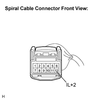
Measure the voltage according to the value(s) in the table below.
- Standard voltage:
Tester connection
Condition
Specified condition
IL+2 - Body ground
Light control SW TAIL or HEAD
10 to 14 V
|
|
||||
| OK | |
|
| 3. CHECK STEERING PAD SWITCH ASSEMBLY |
Disconnect the steering pad switch assembly connector.
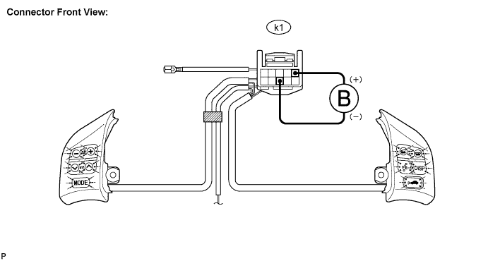
Connect the positive (+) lead to terminal IL+2 and the negative (-) lead to terminal EAU of the steering pad switch assembly connector.
Check if the illumination for the steering pad switch assembly comes on.
- OK:
- Illumination for the steering pad switch assembly comes on.
|
|
||||
| OK | |
|
| 4. CHECK SPIRAL CABLE |
Disconnect the steering pad switch assembly and spiral cable connectors.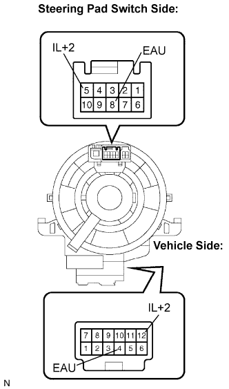
Measure the resistance according to the value(s) in the table below.
- Standard resistance:
Tester Connection
Spiral Cable Position
Specified Condition
EAU - EAU
Center
Below 1 Ω
2.5 rotations to the left
2.5 rotations to the right
IL+2 - IL+2
Center
Below 1 Ω
2.5 rotations to the left
2.5 rotations to the right
- NOTICE:
- The spiral cable is an important part of the SRS airbag system. Incorrect removal or installation of the spiral cable may prevent the airbag from deploying. Be sure to read the page shown in the brackets (Click here).
|
|
||||
| OK | |
|
| 5. CHECK HARNESS AND CONNECTOR (SPIRAL CABLE - RADIO RECEIVER) |
Disconnect the radio receiver and spiral cable connectors.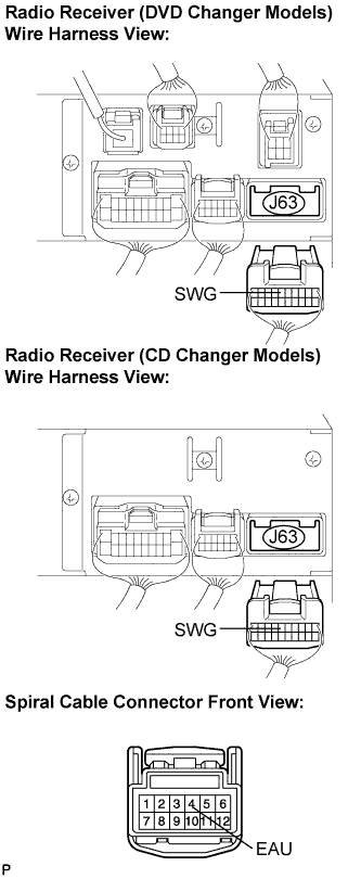
Measure the resistance according to the value(s) in the table below.
- Standard resistance:
Tester connection
Condition
Specified condition
SWG - EAU
Always
Below 1 Ω
SWG - Body ground
Always
10 kΩ or higher
|
|
||||
| OK | ||
 |
||
| ||
| 6. CHECK HARNESS AND CONNECTOR (BATTERY - MULTI-DISPLAY) |
Disconnect the multi-display connector J50.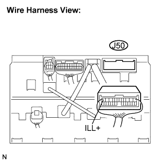
Measure the voltage according to the value(s) in the table below.
- Standard voltage:
Tester connection
Condition
Specified condition
ILL+ - Body ground
Light control switch TAIL or HEAD
10 to 14 V
|
|
||||
| OK | |
|
| 7. CHECK HARNESS AND CONNECTOR (MULTI-DISPLAY - COMBINATION METER) |
Disconnect the multi-display and combination meter connectors.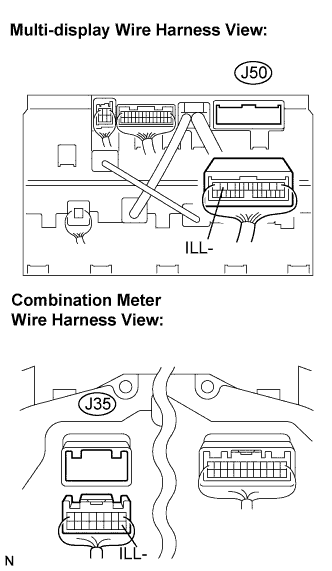
Measure the resistance according to the value(s) in the table below.
- Standard resistance:
Tester connection
Condition
Specified condition
ILL- - ILL-
Always
Below 1 Ω
ILL- - Body ground
Always
10 kΩ or higher
|
|
||||
| OK | ||
|
||
| ||