Steering Pad Switch Circuit
Circuit diagnosis
DESCRIPTION
This circuit sends an operation signal from the steering pad switch to the radio receiver.If there is an open in the circuit, the navigation system cannot be operated using the steering pad switch.
If there is a short in the circuit, the resulting condition is the same as if the switch were continuously depressed. Therefore, the navigation system cannot be operated using the steering pad switch, and the navigation system itself cannot function.
WIRING DIAGRAM
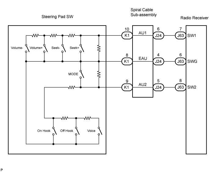

INSPECTION PROCEDURE
- NOTICE:
- The vehicle is equipped with an SRS (Supplemental Restraint System) which includes components such as airbags. Before servicing (including removal or installation of parts), be sure to read the precautionary notice for the Supplemental Restraint System (Click here).
| 1. INSPECT RADIO RECEIVER |

Disconnect the radio receiver connector J63.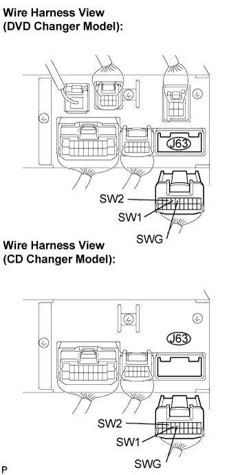
Measure the resistance according to the value(s) in the table below.
- Standard resistance:
Tester connection
Condition
Specified condition
SW1 - SWG
No switch is pushed
Approx. 100 kΩ
SW1 - SWG
SEEK+ switch: push
Approx. 0 Ω
SW1 - SWG
SEEK- switch: push
Approx. 0.3 kΩ
SW1 - SWG
VOL+ switch: push
Approx. 1 kΩ
SW1 - SWG
VOL- switch: push
Approx. 3.2 kΩ
SW2 - SWG
No switch is pushed
Approx. 100 kΩ
SW2 - SWG
MODE switch: push
Approx. 0 Ω
SW2 - SWG
VOICE switch: push
Approx. 3.2 kΩ
SW2 - SWG
ON HOOK switch: push
Approx. 0.3 kΩ
SW2 - SWG
OFF HOOK switch: push
Approx. 1 kΩ
|
|
||||

| OK | ||
 |
||
| ||
| 2. INSPECT STEERING PAD SWITCH ASSEMBLY |
Disconnect the steering pad switch assembly connector K1.
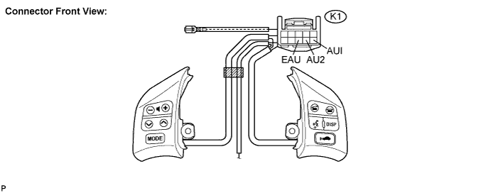
Measure the resistance according to the value(s) in the table below.
- Standard resistance:
Tester connection
Condition
Specified condition
AU1 - EAU
No switch is pushed
Approx. 100 kΩ
AU1 - EAU
SEEK+ switch: push
Approx. 0 Ω
AU1 - EAU
SEEK- switch: push
Approx. 0.3 kΩ
AU1 - EAU
VOL+ switch: push
Approx. 1 kΩ
AU1 - EAU
VOL- switch: push
Approx. 3.2 kΩ
AU2 - EAU
No switch is pushed
Approx. 100 kΩ
AU2 - EAU
MODE switch: push
Approx. 0 Ω
AU2 - EAU
VOICE switch: push
Approx. 3.2 kΩ
AU2 - EAU
ON HOOK switch: push
Approx. 0.3 kΩ
AU2 - EAU
OFF HOOK switch: push
Approx. 1 kΩ
|
|
||||

| OK | |
 |
| 3. INSPECT SPIRAL CABLE |
Disconnect the steering pad switch assembly and spiral cable connectors.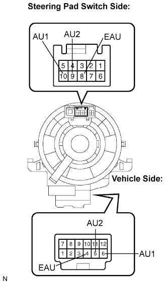
Measure the resistance according to the value(s) in the table below.
- Standard resistance:
Tester connection
Spiral Cable Position
Specified condition
EAU - EAU
Center
Below 1 Ω
2.5 rotations to the left
2.5 rotations to the right
AU1 - AU1
Center
Below 1 Ω
2.5 rotations to the left
2.5 rotations to the right
AU2 - AU2
Center
Below 1 Ω
2.5 rotations to the left
2.5 rotations to the right
- NOTICE:
- The spiral cable is an important part of the SRS airbag system. Incorrect removal or installation of the spiral cable may prevent the airbag from deploying. Be sure to read the page shown in the brackets (Click here).
|
|
||||
| OK | ||
|
||
| ||